
Description
-
Model List:
- ViO70 (US) Excavator
- 1. Vio70(US)
- 2. FOREWORD
- 3. CONTENTS
- 4. GENERAL CAUTIONS FOR MAINTENANCE WORK
- 4.1. Correct Work
- 4.2. Safety Precautions
- 4.3. Preparations
- 4.4. Cautions for Disassembly and Reassembly
- 4.5. Cautions for Attaching and Detaching Hydrauplic Equipment
- 4.6. Cautions for Attaching and Detaching Hydraulic Piping
- 4.7. Cautions for Handling Seals
- 4.8. Correct Installation of Hydraulic Hose
- 4.9. Specifications of Hydraulic Hose
- 4.10. Air-Venting of Hydraulic Equipment
- 5. TECHNICAL DATA
- 5.1. Specifications
- 5.2. External Drawings and Working Ranges
- 5.2.1. Canopy Type Specifications
- 5.3. Weight of Main Parts
- 5.4. Lifting Capacities
- 6. SERVICING STANDARDS
- 6.1. Machine Performance
- 6.2. Engine
- 6.3. Undercarriage
- 6.3.1. Rubber Track Specifications
- 6.3.2. Steel Track Specifications
- 6.3.3. Steel Rubber Track Common Specifications
- 6.4. Control Devices
- 6.5. Hydraulic Equipment
- 6.5.1. Hydraulic Cylinder
- 6.6. Work Implement
- 6.6.1. Front Attachment
- 6.6.2. Blade Moving Device
- 6.6.3. Bucket Teeth
- 6.7. Torque Specifications
- 6.7.1. Machine
- 6.7.2. Engine
- 6.7.3. Tightening Torque of General Bolts and Nuts
- 7. HYDRAULIC SYSTEM
- 7.1. Outline
- 7.1.1. Function of Control Valve Operation
- 7.1.2. Additional Operation of Control Valve
- 7.2. Hydraulic Circuit Schematic
- 7.3. Operating Circuit
- 7.3.1. Boom
- 7.3.2. Arm
- 7.3.3. Bucket
- 7.3.4. Swing
- 7.3.5. Boom Swing
- 7.3.6. Blade
- 7.3.7. Traveling
- 7.3.8. Simultaneous Operation of Travel and Boom/Bucket
- 7.3.9. Simultaneous Operation of Travel and Arm/Boom Swing
- 7.3.10. Simultaneous Operation of Boom-Up and Arm-Down
- 7.3.11. Simultaneous Operation of Boom-Up and Bucket
- 7.3.12. Simultaneous Operation of Boom-Up and Swing
- 7.3.13. Hydraulic P.T.O.
- 7.4. Pressure Adjustment
- 7.4.1. Relief Valves
- 7.4.2. Swing Brake Valve
- 7.4.3. Cut-off Valve
- 8. HYDRAULIC EQUIPMENT
- 8.1. Hydraulic Pump
- 8.2. Control Valve
- 8.3. Pilot Valve
- 8.4. Swing Motor
- 8.5. Travel Motor
- 9. ADJUSTMENT PROCEDURES FOR EACH EQUIPMENT
- 9.1. Electric Equipment of the Machine
- 9.1.1. Arrangement of Electrical Equipment and Names of Parts
- 9.1.2. Monitor and Alarm Systems
- 9.1.3. Electric Wiring Diagram
- 9.2. Undercarriage
- 9.2.1. Outline
- 9.2.2. Major Parts
- 9.2.3. Cautions for Reassembly (Rubber Track)
- 9.2.4. Cautions for Reassembly (Steel Track)
- 9.2.5. Disassembly and Reassembly of Idler
- 9.2.6. Assembly of Idler
- 9.2.7. Disassembly and Reassembly of Track Roller
- 9.2.8. Disassembly and Reassembly of Carrier Roller
- 9.3. Controls
- 9.3.1. Control Train
- 9.3.2. Disassembly and Reassembly of Mecahnical Control Linkages
- 9.3.3. Adjustment of Implements Control Levers
- 9.3.4. Adjustment of Travel Levers
- 9.3.5. Adjustment of 2-Speed Pedal
- 9.3.6. Adjustment of Boom Swing Pedal
- 9.3.7. Adjustment of Blade Lever
- 9.3.8. Adjustment of Lock Lever
- 9.3.9. Adjustment of Engine Speed Control Lever
- 9.4. Swing System
- 9.4.1. Swing Bearing
- 9.5. Hydraulic Equipment
- 9.5.1. Precautions for Removal and Installation,and Assembly of Hydraulic Pump
- 9.5.2. Disassembly and Reassembly of Hydraulic Cylinder
- 9.5.3. Swivel Joint
- 9.5.4. Hydraulic Oil Tank
- 9.5.5. Hydraulic Piping Layout
- 9.6. Cabin and Cab guard
- 9.6.1. Weight of Components
- 9.6.2. Disassembly Procedure for Cab guard
- 9.6.3. Reassembly Procedure for Cab guaed
- 9.6.4. Disassembly and Reassembly Procedure for Cabin
- 10. PERIODIC INSPECTION AND SERVICING
- 10.1. List of Periodic Inspection and Servicing
- 11. FUEL,LUBE OIL AND GREASE RECOMMENDED
- 11.1. Fuel,Lube Oil and Grease Recommended by Yanmar
- 11.2. Cooling Water Recommended by Yanmar
- 12. TROUBLESHOOTING
- 12.1. Non-breakdowns
- 12.1.1. Natural Release of Bucket
- 12.1.2. Discontinuous Arm Movement
- 12.1.3. Thermal Shock of Travel Motor
- 12.1.4. Elongation of Boom Swing Cylinder on 68 degrees Swing
- 12.1.5. Time Lag on Switching Travel Speed
- 12.1.6. Hydraulic Oil Tank Oil Level Fluctuation Through Temperature Change
- 12.2. Thoubleshooting
- 12.2.1. Machine and Engine
- 12.2.2. Electrical Equipment on Panel
- 13. REFERENCE DATA
- 13.1. Specifications for Attachment
- 14. DIESEL ENGINE
- 14.1. FOREWORD
- 14.2. For Safe Servicing
- 14.3. Precautions for Safe Servicing
- 14.4. CONTENTS
- 14.5. GENERAL
- 14.5.1. How to Read This Manual
- 14.5.2. Precautions for Service Work
- 14.6. TROUBLESHOOTING
- 14.6.1. Quick Reference Table for Troubleshooting
- 14.6.2. Troubleshooting By Measuring Compression Pressure
- 14.7. ENGINE BODY
- 14.7.1. Oil Inspection
- 14.7.2. Cooling Water Inspection
- 14.7.3. Inspecting Water Leak from Cooling Water System and Radiator
- 14.7.4. Fan Belt Tension Inspection and Adjustment
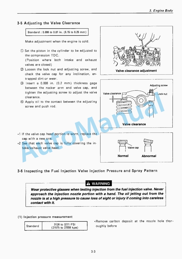
- 14.7.5. Adjustment the Valve Clearance
- 14.7.6. Inspecting the Fuel Injection Valve Injection Pressure and Pattern
- 14.7.7. Fuel Injection Timing Inspection and Adjustment
- 14.7.8. Sensor Inspection
- 14.7.9. Battery Inspection
- 14.7.10. Adjustment Operation
- 14.7.11. Long Storage
- 14.7.12. Periodic Maintenance Schedule
- 14.8. ENGINE BODY
- 14.8.1. Introduction
- 14.8.2. Cylinder Head
- 14.8.3. Gear Train and Camshaft
- 14.8.4. Cylinder Block
- 14.9. LUBRICATION SYSTEM
- 14.9.1. Lubrication System Diagram
- 14.9.2. Trochoid Pump Components
- 14.9.3. Disassembly
- 14.9.4. Servicing Points
- 14.9.5. Parts Inspection and Measurement
- 14.10. COOLING SYSTEM
- 14.10.1. Cooling Water System
- 14.10.2. Cooling Water Pump Components
- 14.10.3. Disassembly
- 14.10.4. Servicing Points
- 14.11. FUEL INJECTION PUMP/GOVERNOR
- 14.11.1. Introduction
- 14.11.2. Fuel Injection Pump
- 14.11.3. Fuel Injection Valve
- 14.11.4. Fuel Feed Pump
- 14.11.5. Governor
- 14.11.6. Special Service Tools for Disassembly/Assembly
- 14.12. STARTING MOTOR
- 14.12.1. Specifications
- 14.12.2. Components
- 14.12.3. Troubleshooting
- 14.12.4. Names of Parts and Disassembly Procedure
- 14.12.5. Inspection and Maintenance
- 14.12.6. Service Standards
- 14.12.7. Assembly
- 14.12.8. Characteristic Test
- 14.13. ALTERNATOR
- 14.13.1. Specifications
- 14.13.2. Section View
- 14.13.3. Troubleshooting
- 14.13.4. Parts Names and Disassembly Procedure
- 14.13.5. Inspection and overhaul
- 14.13.6. Assembly
- 14.13.7. Service Standards
- 14.13.8. Performance Test
- 14.14. SPECIAL SERVICE TOOLS
- 14.14.1. Special Tools
- 14.14.2. Measuring Instruments
- 14.15. SERVICE STANDARDS
- 14.15.1. Engine Turning
- 14.15.2. Engine Body
- 14.15.3. Lubricating Oil System (Trochoid pump)
- 14.15.4. Tightening Torques for Main Parts
%20Excavator%20Service%20Manual&url=https://pdfrepairmanual.com/docs/yanmar-vio70-us-excavator-service-manual/&media=https://pdfrepairmanual.com/wp-content/uploads/2026/01/yanmar-vio70-us-excavator-service-manual-1.jpg)


,%202GM(F)(L),%203GM(D)(F)(L),%203HM(F)(L)%20Engine%20Service%20Manual&url=https://pdfrepairmanual.com/docs/yanmar-1gm10l-2gmfl-3gmdfl-3hmfl-engine-service-manual/&media=https://pdfrepairmanual.com/wp-content/uploads/2026/01/yanmar-1gm10l-2gmfl-3gmdfl-3hmfl-engine-service-manual-1.jpg)


There are no reviews yet.