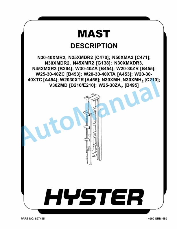
Hyster N30-40XMR2 to W25-30ZA2 Mast Description Maintenance And Repair
$30.00
- Type Of Manual: Maintenance And Repair
- Number of Pages: 856
- Size: 66.1MB
- Format: PDF
Description
-
Model List:
- N30-40XMR2, N25XMDR2, N50XMA2, N30XMDR2, N45XMR2, N30XMXDR3, N45XMXR3, W30-40ZA, W20-30ZR, W25-30-40ZC, W20-30-40XTA, W20-30-40XTC, W2030XTR, N30XMH, N30XMH2, V30ZMD, W25-30ZA2
- 1. RM0480-(04-2008)-US-EN
- 1.1. Safety Precautions Maintenance and Repair
- 1.2. General
- 1.3. Mast Weldments
- 1.4. Carriages
- 1.5. Two-Stage Mast
- 1.6. Description
- 1.7. Operation
- 1.8. Three-Stage Mast
- 1.9. Description
- 1.10. Operation
- 2. RM0481-(07-2013)-US-EN
- 2.1. Lift Cylinders
- 2.2. Safety Precautions Maintenance and Repair
- 2.3. General
- 2.4. Description
- 2.5. Lowering Control Valve
- 2.6. Main Cylinder Repair
- 2.7. Disassemble
- 2.8. Assemble
- 2.9. Free-Lift Cylinder Repair
- 2.10. Disassemble
- 2.11. Assemble
- 2.12. Troubleshooting
- 3. RM0482-(04-2008)-US-EN
- 3.1. Safety Precautions Maintenance and Repair
- 3.2. General
- 3.3. Safety Procedures When Working Near Mast
- 3.4. Load Backrest Extension, Carriage, Load Rollers, Side Rollers, a
- 3.5. Load Backrest Extension, Remove and Install
- 3.6. Carriage Assembly, Remove and Install
- 3.7. Carriage Load Rollers, Remove and Install
- 3.8. Side Rollers, Disassemble and Assemble
- 3.9. Fork, Replace
- 3.10. Hook-Type Forks
- 3.11. Two-Stage Mast Assembly
- 3.12. Clean and Inspect
- 3.13. Lift Cylinders, Remove and Install Dual-Lift Cylinders
- 3.14. Lift Cylinder, Remove and Install Single Main-Lift Cylinders
- 3.15. Install
- 3.16. Inner Mast Assembly, Remove and Install
- 3.17. Hoses, Replace
- 3.18. Hose and Cable Sheaves, Replace
- 3.19. Two-Stage Lift Chains
- 3.20. Remove and Install
- 3.21. Clean and Inspect
- 3.22. Two-Stage Chain Sheave, Remove and Install
- 3.23. Load Rollers and Wear Plugs, Remove and Install
- 3.24. Two-Stage Mast Assembly, Install
- 3.25. Three-Stage Mast Assembly
- 3.26. Three-Stage Mast Assembly, Remove
- 3.27. N30XHM, N30XMH 2 (C210), and V30ZMD (D210/E210) Only
- 3.28. Clean and Inspect
- 3.29. Free-Lift Cylinder, Remove and Install
- 3.30. Main Cylinders (Standard), Remove and Install
- 3.31. Main Cylinders N30XMH, N30XMH 2 (C210) and V30ZMD (D210/E210), R
- 3.32. Inner and Intermediate Mast Assemblies, Remove and Install
- 3.33. Hoses, Replace
- 3.34. Hose and Cable Sheaves, Replace
- 3.35. Free-Lift Hose Sheave
- 3.36. Carriage Sheaves
- 3.37. Three-Stage Lift Chains, Remove and Install
- 3.38. General
- 3.39. Free-Lift Chains
- 3.40. Main-Lift Chains
- 3.41. Three-Stage Chain Sheaves, Disassemble and Assemble
- 3.42. Free-Lift Chain Sheaves
- 3.43. Main-Lift Chain Sheaves
- 3.44. Load Rollers and Wear Plugs, Remove and Install
- 3.45. Three-Stage Mast Assemble, Install
- 3.46. Mast Operation Check
- 3.47. Hydraulic System Leaks Check
- 3.48. Lift Chains Check
- 3.49. General
- 3.50. Clean and Inspect
- 3.51. Lubrication
- 3.52. Mast Adjustments
- 3.53. General
- 3.54. Adjust Wear Plugs – Mast
- 3.55. Adjust Free-Lift Chain (Three-Stage Only)
- 3.56. Adjust Main-Lift Chains
- 3.57. Two-Stage
- 3.58. Three-Stage
- 3.59. Adjust Wear Strips
- 3.60. Carriage Adjustments
- 3.61. Adjust Wear Plug – Carriage
- 3.62. Adjust Side Rollers – Carriage
- 3.63. Adjust Thrust Rollers – Carriage
- 3.64. Troubleshooting
- 4. RM0514-(01-2004)-US-EN
- 4.1. Instrument Cluster
- 4.2. Safety Precautions Maintenance and Repair
- 4.3. General
- 4.4. Description
- 4.5. Display Panels on Steering Column, Internal Combustion
- 4.6. Display Panels on Steering Column, Electric Lift Trucks
- 4.7. Standard Display Panel
- 4.8. Enhanced Display Panel
- 4.9. Curtis 1215 Display Panel
- 4.10. Description and Features
- 4.11. Operation
- 4.12. Cluster-Type Display Panel (Internal Combustion) Replacement
- 4.13. Remove and Disassemble
- 4.14. Assemble and Install
- 4.15. Cluster Display Panel (Electric Lift Truck) Replacement
- 4.16. Display Panel Assembly, Replace
- 4.17. LED Indicators
- 4.18. Battery Indicators
- 4.19. Digital Display (Enhanced Display Panel Only)
- 4.20. Status Code or Performance Level Switches and LED indicators (En
- 4.21. Standard Display Panel Parts, Replace
- 4.22. Enhanced Display Panel Parts, Replace
- 4.23. Curtis 1215 Display Panel Replacement
- 4.24. Install
- 4.25. Table 1. Instrument Cluster, Internal Combustion
- 5. RM0578-(05-1998)-US-EN
- 6. RM0579-(12-1997)-US-EN
- 7. RM0604-(05-1999)-US-EN
- 8. RM0605-(05-1999)-US-EN
- 9. RM0606-(05-1998)-US-EN
- 10. RM0607-(12-1995)-US-EN
- 11. RM0608-(01-1996)-US-EN
- 12. RM0609-(04-1996)-US-EN
- 13. RM0610-(05-1999)-US-EN
- 14. RM0001-(01-2016)-US-EN
- 14.1. General
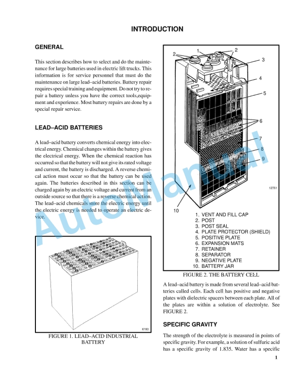
- 14.2. Lead-Acid Batteries
- 14.3. Specific Gravity
- 14.4. Chemical Reaction in a Cell
- 14.5. Electrical Terms
- 14.6. Battery Selection
- 14.7. Battery Voltage
- 14.8. Battery as a Counterweight
- 14.9. Battery Ratings
- 14.10. Battery Maintenance
- 14.11. Troubleshooting
- 15. RM0103-(03-2007)-US-EN
- 15.1. Tilt Cylinders
- 15.2. Safety Precautions Maintenance and Repair
- 15.3. General
- 15.4. Description
- 15.5. Tilt Cylinder Repair
- 15.6. Disassemble
- 15.7. Assemble
- 15.8. Tilt Cylinders With O-Ring or Single-Lip Seals
- 15.9. Tilt Cylinders for XM and XMS Models
- 15.10. Tilt Cylinders for XL, XLS, and XL 3 Models
- 15.11. Tilt Cylinders for H700-800A and Early Model H700-920B
- 15.12. Install
- 15.13. Tilt Cylinders Using Chevron Packing
- 15.14. Tilt Cylinder Leak Check
- 15.15. Tilt Cylinder Stroke and Mast Tilt Angle Adjustment
- 15.16. Torque Specifications
- 15.17. Piston Rod Nut
- 15.18. Retainer
- 15.19. Troubleshooting
- 15.20. Table 1. Movement Rates (Maximum) for Tilt Cylinders
- 16. RM0138-(10-2005)-US-EN
- 16.1. Battery Indicators
- 16.2. Safety Precautions Maintenance and Repair
- 16.3. General
- 16.4. Indicators With Meter Movements
- 16.5. Battery Indicators With LCD or LED Displays
- 16.6. Liquid Crystal Displays
- 16.7. SEM Display Panels Description
- 16.8. Light Emitting Diode Displays
- 16.9. Description LX Series
- 16.10. ZX Series Display Panels Description
- 16.11. SEVCON POWERGAUGE Battery Display Panel Description
- 16.12. Battery Indicators Without Lift Interrupt Adjustment (Early Mode
- 16.13. Battery Indicators With Lift Interrupt Adjustment (Early Models)
- 16.14. Reset Potentiometer
- 16.15. Specific Gravity Alarm
- 16.16. Battery Indicators Without Lift Interrupt Check (Later Models)
- 16.17. Battery Indicators With Lift Interrupt Adjustment (Later Models)
- 16.18. Reset Potentiometer
- 16.19. Discharge Potentiometer
- 16.20. LED Display With Lift Interrupt
- 16.21. Curtis 933-1 Meter Check and Adjustment
- 16.22. Reset Check
- 16.23. Discharge Check
- 16.24. Lockout Check
- 16.25. LEDs Do Not Illuminate
- 16.26. Hourmeter Check
- 16.27. Hourglass Icon
- 16.28. SEVCON POWERGAUGE Adjustment
- 16.29. Curtis Dash Display Assembly
- 16.30. Description/Features
- 16.31. Operation
- 16.32. Testing
- 16.33. Inoperative Dash Display Assembly
- 16.34. Inoperative Drive Mode Selection
- 16.35. Troubleshooting With a Programmer Handset
- 16.36. Troubleshooting Without a Programmer Handset
- 16.37. No Warnings or Faults Displayed
- 16.38. MIB/Dash Display Communication
- 16.39. Lift Interrupt
- 16.40. Lost MIB Signal Displayed
- 16.41. Lift Pump Hourmeter Input
- 16.42. Forward/Reverse Hourmeter Inputs
- 16.43. Install
- 16.44. Adjust (Setup, Early Models)
- 16.45. Adjust (Setup, Later Model)
- 16.46. Battery Indicators Replacement
- 16.47. Battery Indicator Controller Replacement
- 16.48. Display Panel Components Replacement
- 16.49. SEM Display Panel Replacement
- 16.50. Remove and Replace
- 16.51. Table 1. Battery Indicator (Later Models)
- 16.52. Table 2. SEVCON Discharge Curve Selector Positions
- 16.53. Table 3. Dash Display Drive Mode Inputs
- 16.54. Table 4. Dash Display Drive Mode Test Voltages
- 16.55. Table 5. Dash Display Status/Warning/Fault Test Voltages
- 16.56. Table 6. Testing Dash Display Status/Warning/Fault Inputs
- 16.57. Table 7. Battery Indicator Reset Adjustment
- 17. RM0231-(01-2016)-US-EN
- 17.1. General
- 18. RM0689-(05-1999)-US-EN
- 19. RM0690-(05-1998)-US-EN
- 20. RM0718-(06-1998)-US-EN
- 21. RM0719-(05-1999)-US-EN
- 22. RM0748-(05-1999)-US-EN
- 23. RM0750-(05-1999)-US-EN
- 24. RM0758-(05-1999)-US-EN
- 25. RM0759-(05-1999)-US-EN



%20Service%20Manual&url=https://pdfrepairmanual.com/docs/hyster-a406-r1-4-r1-6-service-manual/&media=https://pdfrepairmanual.com/wp-content/uploads/2026/01/hyster-a406-r14-r16-service-manual-1.jpg)
%20Service%20Manual&url=https://pdfrepairmanual.com/docs/hyster-b174-r30es-service-manual/&media=https://pdfrepairmanual.com/wp-content/uploads/2026/01/hyster-b174-r30es-service-manual-1.jpg)


%20Maintenance%20Schedule&url=https://pdfrepairmanual.com/docs/hyster-c098-e3-50-5-50xl-e4-50xls-maintenance-schedule/&media=https://pdfrepairmanual.com/wp-content/uploads/2026/01/hyster-c098-e350-550xl-e450xls-maintenance-schedule-1.jpg)
%20Service%20Manual&url=https://pdfrepairmanual.com/docs/hyster-c098-e3-50-5-50xl-service-manual/&media=https://pdfrepairmanual.com/wp-content/uploads/2026/01/hyster-c098-e350-550xl-service-manual-1.jpg)
%20Service%20Manual&url=https://pdfrepairmanual.com/docs/hyster-b460-k1-0m-k1-0h-k1-0h-wp-service-manual/&media=https://pdfrepairmanual.com/wp-content/uploads/2026/01/hyster-b460-k10m-k10h-k10h-wp-service-manual-1.jpg)

There are no reviews yet.