

Description
-
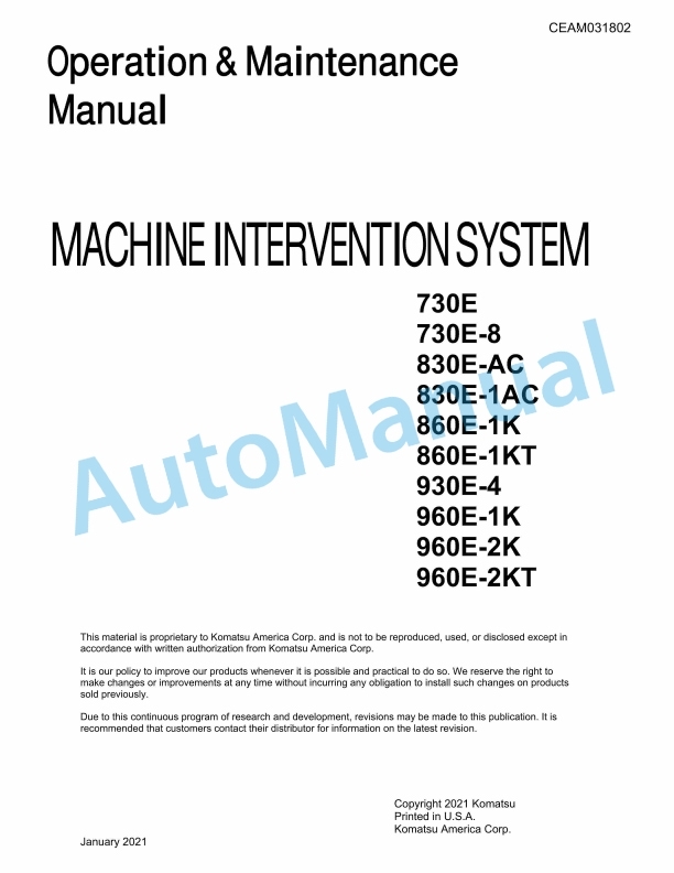
Model List:
- 730E Machine Intervention System
- 730E-8 Machine Intervention System
- 830E-AC Machine Intervention System
- 830E-1AC Machine Intervention System
- 860E-1K Machine Intervention System
- 860E-1KT Machine Intervention System
- 930E-4 Machine Intervention System
- 960E-1K Machine Intervention System
- 960E-2K Machine Intervention System
- 960E-2KT Machine Intervention System
- 1. LEGAL WAIVER
- 1.1. Limitations of the Machine Intervention System
- 1.2. Braking Intervention
- 1.3. Situations in which the MIS may not operate properly
- 1.4. MIS warning panel system light turns red
- 2. INTRODUCTION
- 2.1. Forward
- 2.2. Machine Intervention Controller Data Recordings
- 2.3. Data Usage
- 2.4. About this Manual
- 2.5. Alerts Page
- 3. TABLE OF CONTENTS
- 4. MACHINE INTERVENTION CONTROLLER
- 4.1. General Information
- 4.2. Component Description
- 4.3. Intervention Circuits
- 4.4. Override Switch
- 4.5. Indicator Panel
- 4.5.1. Indicator Panel Symbols
- 4.6. System Status
- 4.7. Forward Propel Inhibit
- 4.8. BodyUp Inhibit
- 4.9. Braking Status
- 4.10. Reverse Propel Inhibit
- 4.11. Engine Crank Inhibit
- 4.12. Drowsiness Detection
- 4.12.1. Special Tools
- 4.13. Wiring Harness, Bypass
- 4.14. Cable, CAT5E PLM4
- 4.15. Template, Cab Bottom
- 5. UPDATING THE MIC FIRMWARE
- 5.1. To update the MIC firmware
- 5.1.1. Prepare a USB flash drive
- 5.1.2. Update the firmware
- 6. SYSTEM CONFIGURATION
- 6.1. Connecting to the MIC Web Server
- 6.2. Configuring Static IP Address
- 6.3. Real Time Data
- 6.4. Machine Intervention Controller System Configuration
- 6.5. Retarder Output Calibration
- 6.6. Controller Removal
- 6.6.1. Machine Intervention Controller Intervention Checkout
- 6.7. Available inhibitions are
- 6.8. Description of Event Logger Items
- 7. TROUBLESHOOTING FAULT CODES
- 7.1. M001 Forward Propel Inhibit Fault
- 7.2. M002 Reverse Propel Inhibit Fault
- 7.3. M003 Hoist Inhibit Fault
- 7.4. M004 Starter Inhibit Fault
- 7.5. M005 Remote Shutdown Fault
- 7.6. M006 Retarder Output Fault
- 7.7. M007 Auto Apply Output Fault
- 7.8. M011 MIC has experienced an unexpected power loss
- 7.9. M012 MIC Loss of Indicator Panel Communication
- 7.10. M058 3rd Party Controller CAS Geofence Radar Fault
- 7.11. M059 3rd Party Controller CAS Geofence GPS Fault
- 7.12. M060 3rd Party Controller CAS Geofence RF Communications Fault
- 7.13. M061 3rd Party Controller CAS Geofence System Fault
- 7.14. M062 Loss of 3rd Party Controller CAS Geofence Communication
- 7.15. M063 3rd Party Controller Take Off Protection Rear Radar Fault
- 7.16. M064 3rd Party Controller Take Off Protection Front Radar Fault
- 7.17. M065 3rd Party Controller Take Off Protection GPS Fault
- 7.18. M066 3rd Party Controller Take Off Protection RF System Fault
- 7.19. M067 3rd Party Controller Take Off Protection System Fault
- 7.20. M068 Loss of 3rd Party Controller Take Off Protection Communication
- 7.21. M069 Loss of 3rd Party Controller Camera Fault
- 7.22. M070 3rd Party Controller Drowsiness Detection System Fault
- 7.23. M071 Loss of 3rd Party Controller Drowsiness Detection System Communication
- 7.24. M072 3rd Party Controller Operator Licensing RF Communication Fault
- 7.25. M073 3rd Party Controller Operator Licensing System Fault
- 7.26. M074 Loss of 3rd Party Controller Operator Licensing System Communication
- 7.27. M076 Loss of 3rd Party Controller or MMS Vehicle Position Communication
- 7.28. M078 No Message Received by MIC on Safety Subnet
- 7.29. M079 Override Switch Input on for >240 Seconds
- 7.30. M080 No Message, or Failure to Receive Message, from RPC Bus for >3 Seconds
- 7.31. M088 Loss of 3rd party Takeoff Protection inhibits because 3rd party controller is malfunctioning
- 7.32. M089 Loss of 3rd party CAS Geofenced Restrictions inhibits because 3rd party controller is malfunctioning
- 7.33. M090 Loss of 3rd party Drowsiness Detection warnings because 3rd party controller is malfunctioning
- 7.34. M091 Loss of 3rd party Operator Licensing inhibits because 3rd party controller is malfunctioning
- 7.35. M092 F211 from 3rd party is exhibiting unacceptable behavior such as rapid toggling of intervention
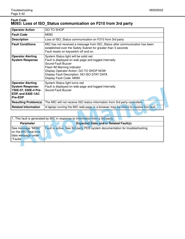
- 7.36. M093 Loss of ISO_Status communication on F210 from 3rd party
- 7.37. M094 Loss of ISO_Command communication on F210 from 3rd party
- 7.38. M095 MIC filesystem fails to initialize properly
- 7.39. NONE MIC Total Communication Loss
- 7.40. NONE MIC Intervention wont Release
- 8. CHECKOUT PROCEDURE
- 8.1. General Information on System Checkout
- 8.2. Scope
- 8.3. Data to Record
- 8.4. Install the Application Code
- 8.5. Required Equipment
- 8.6. Precheckout Items
- 8.6.1. Precheckout Item 1
- 8.6.2. Precheckout Item 2
- 8.6.3. Precheckout Item 3
- 8.6.4. Precheckout Item 4
- 8.6.5. Precheckout Item 5
- 8.6.6. Precheckout Item 6
- 8.6.7. Precheckout Item 7
- 8.6.8. Precheckout Item 8
- 8.6.9. Precheckout Item 9
- 8.6.10. Establish Truck Baseline
- 8.6.11. MIS Hydraulic setup
- 8.6.12. System Verification
- 8.6.13. Manual, MIS 730E Data Sheet
- 9. K and 960EK CHECKOUT PROCEDURE
- 9.1. General Information on System Checkout
- 9.2. Install the Application Code
- 9.3. Required Equipment
- 9.4. Precheckout Items
- 9.4.1. Precheckout Item 1
- 9.4.2. Precheckout Item 2
- 9.4.3. Precheckout Item 3
- 9.4.4. Precheckout Item 4
- 9.4.5. Precheckout Item 5
- 9.4.6. Precheckout Item 6
- 9.4.7. Precheckout Item 7
- 9.4.8. Precheckout Item 8
- 9.4.9. Precheckout Item 9
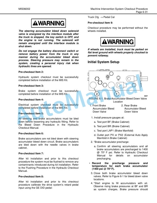
- 9.4.10. Initial System Setup
- 9.4.11. System Verification
- 9.4.12. Hydraulic System Checkout Procedure Data Sheet
- 10. CHECKOUT PROCEDURE
- 10.1. General Information on System Checkout
- 10.2. Scope
- 10.3. Data to Record
- 10.4. Install the Application Code
- 10.5. Required Equipment
- 10.6. Precheckout Items
- 10.6.1. Precheckout Item 1
- 10.6.2. Precheckout Item 2
- 10.6.3. Precheckout Item 3
- 10.6.4. Precheckout Item 4
- 10.6.5. Precheckout Item 5
- 10.6.6. Precheckout Item 6
- 10.6.7. Precheckout Item 7
- 10.6.8. Precheckout Item 8
- 10.6.9. Precheckout Item 9
- 10.6.10. Initial System Setup
- 10.6.11. System Verification
- 10.6.12. Manual, MIS 730E8 Data Sheet
- 11. C CHECKOUT PROCEDURE
- 11.1. General Information on System Checkout
- 11.2. Scope
- 11.3. Data to Record
- 11.4. Install the Application Code
- 11.5. Required Equipment
- 11.6. Precheckout Items
- 11.6.1. Precheckout Item 1
- 11.6.2. Precheckout Item 2
- 11.6.3. Precheckout Item 3
- 11.6.4. Precheckout Item 4
- 11.6.5. Precheckout Item 5
- 11.6.6. Precheckout Item 6
- 11.6.7. Precheckout Item 7
- 11.6.8. Precheckout Item 8
- 11.6.9. Precheckout Item 9
- 11.6.10. Initial System Setup
- 11.6.11. System Verification
- 11.6.12. Manual, MIS 830E1AC Data Sheet
- 12. CHECKOUT PROCEDURE
- 12.1. General Information on System Checkout
- 12.2. Scope
- 12.3. Data to Record
- 12.4. Install the Application Code
- 12.5. Required Equipment
- 12.6. Precheckout Items
- 12.6.1. Precheckout Item 1
- 12.6.2. Precheckout Item 2
- 12.6.3. Precheckout Item 3
- 12.6.4. Precheckout Item 4
- 12.6.5. Precheckout Item 5
- 12.6.6. Precheckout Item 6
- 12.6.7. Precheckout Item 7
- 12.6.8. Precheckout Item 8
- 12.6.9. Precheckout Item 9
- 12.6.10. Initial System Setup
- 12.6.11. System Verification
- 12.6.12. Manual, MIS 930E4 Data Sheet
- 13. SYSTEM SCHEMATICS INDEX
- 13.1. Hydraulic Schematic
- 13.2. Electrical Schematic
- 13.3. Cab Controller Installation (2 OF 2)
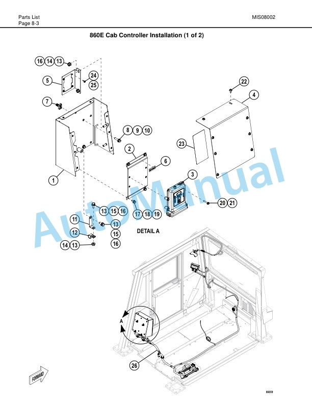
- 13.4. Cab Controller Installation (1 of 2)
- 13.5. MIC Hydraulic Brake Cabinet Kit (860E)
- 13.6. MIC Hydraulic Brake Cabinet Kit (960E)
- 13.7. MIC Controller Wiring (860E)
- 13.8. MIC Controller Wiring (960E)
- 14. PARTS LIST
- 14.1. Component Locations
- 14.2. Component Locations
- 14.3. Cab Controller Installation (2 of 2)
- 14.4. MIC Hydraulic Brake Cabinet Kit (730E 730E8)
- 14.5. MIC Controller Wiring (730E)
- 14.6. MIC Controller Wiring (730E8)
- 14.7. Cab Controller Installation (1 of 2)
- 14.8. AC/830E1AC/930E4 Component Locations
- 14.9. MIC Controller Wiring (830E1/830E1AC)
- 14.10. AC/830E1AC/930E4 Cab Controller Installation (1 of 2)
- 14.11. AC/830E1AC/930E4 Cab Controller Installation (2 of 2)
- 14.12. MIC Hydraulic Brake Cabinet Kit (830EAC 830E1AC)
- 14.13. MIC Hydraulic Brake Cabinet Kit (930E4)
- 14.14. MIC Controller Wiring (930E4)




There are no reviews yet.