
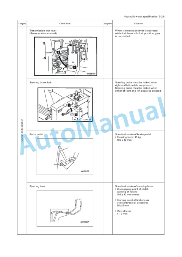
Description
-
Model List:
- D355C-3 Pipe Layer
- 1. COVER
- 2. Preface
- 3. CONTENTS
- 3.1. SPECIFICATIONS
- 3.2. PRECAUTIONS FOR FIELD ASSEMBLY
- 3.2.1. Selection of workplace
- 3.2.2. Preparation and check of slings and tools
- 3.2.3. kCheck of actual work
- 3.2.4. Before starting the work, layout the parts to be assembled.
- 3.2.5. Before starting the work, read this manual thoroughly and keep the precautions in your mind.
- 3.2.6. The supervisor shall write down the precautions for each work process and explain them to the workers.
- 3.2.7. Hold a meeting every morning to check todays work plan and safe work. Precaution When assembling, refer to the operation manual as well as this manual.
- 3.3. ASSEMBLY PROCEDURE, NECESSARY EQUIPMENT, AND SCHEDULE
- 3.4. POSITION FOR TRANSPORTATION
- 3.4.1. Chassis
- 3.4.2. Boom assembly
- 3.4.3. Counterweight bracket assembly
- 3.4.4. Counterweight
- 3.4.5. Frame (Boom side)
- 3.4.6. Lift link (Large)
- 3.4.7. Frame (Winch side)
- 3.4.8. Removed parts
- 3.4.10. Exterior parts (for hydraulic winch specification only
- 3.5. LIST OF TOOLS FOR FIELD ASSEMBLY
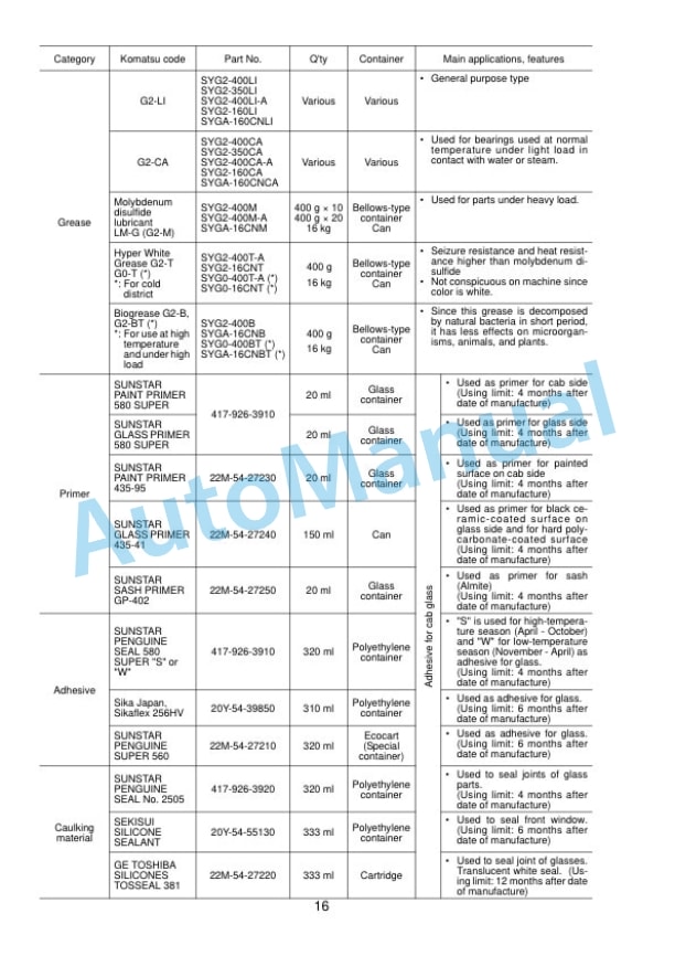
- 3.6. COATING MATERIALS LIST
- 3.6.1. Remove the rain cap (used for transportation) and install exhaust pipe (1).
- 3.6.2. Install rain cap (20Y0112300).
- 3.6.3. Installation of head lamp
- 3.6.4. Installation of side lamp
- 3.6.5. Install frame (on the winch side) (2) on the right side of the chassis carefully.
- 3.6.6. Taking care of the following points, install frame (on the boom side) (3) on the left side of the chassis.
- 3.6.7. Adjusting boom kickout
- 3.6.8. Install large link (9), small link (10), front cylinder (11) 50C specification (13), and rear cylinder (12) 50C specification (14) to bracket (8) to make the subassembly.
- 3.6.9. With the engine stopped, set the counterweight control lever in the RETRACT and EXTRACT positions 2 3 times to release the residual pressure in the cylinder piping.
- 3.6.10. Sling the subassembly in 1 above and install it to the gatetype frame according to the following procedure.
- 3.6.11. Connect the cylinder piping. Remove the oil stop plugs of the cylinder and tubes and install the hydraulic hoses, taking care…
- 3.6.12. Supply grease to each part. (See A10 Greasing)
- 3.6.13. After finishing the installation work, bleed air from each cylinder according to the following procedure, and then check the hydraulic oil level.
- 3.6.14. After installing the counterweight, operate the counterweight control lever to check that the hydraulic hoses do not interfere with other parts and oil is not leaking.
- 3.6.15. Install the counterweight segment securely according to the following procedure.
- 3.6.16. Installation of head lamp (For only machine for CIS)
- 3.6.17. Installation of cab
- 3.6.18. Installation of hot water heater pipes
- 3.6.19. Installation of cab power supply
- 3.6.20. Install the floor mats (1), (2).
- 3.6.21. Installation of accessories
- 3.6.22. Installation of air conditioner piping
- 3.6.23. Installation of overwind prevention device (if equipped)
- 3.6.24. Installation of angle indicator and hook stabilizer rope
- 3.6.25. Installation of wire rope retainer lock (If equipped)
- 3.6.26. Check of hot water circuit of heater
- 3.6.27. Wiring in dashboard
- 3.6.28. Check of power supply
- 3.6.29. Charging with refrigerant
- 3.6.30. Wiring around compressor
- 3.6.31. Using a grease pump, supply grease to the grease fittings indicated by arrows.
- 3.6.32. After supplying grease, wipe off the projected grease.
- 3.6.33. Installation of handrail around battery case (rear left of machine).
- 3.6.34. Installation of step and mirror (rear right of machine).
- 3.6.35. Counterweight cylinder
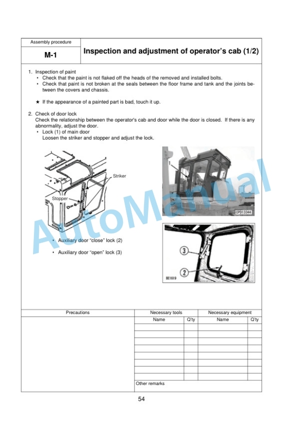
- 3.6.36. Inspection of paint
- 3.6.37. Check of door lock
- 3.6.38. Check of OPEN lock (if equipped)
- 3.6.39. Inspection of boom kickout
- 3.6.40. Check of operation of moment limiter (if equipped)
- 3.6.41. Check of operation of moment limiter (if equipped)
- 3.6.42. Check of operation of overwind prevention device (if equipped)







There are no reviews yet.