

Description
-
Model List:
- PC1250-11R Hydraulic Excavator
- PC1250SP-11R Hydraulic Excavator
- 1. COVER
- 2. SPECIFICATIONS
- 3. PRECAUTIONS FOR FIELD ASSEMBLY
- 4. ASSEMBLING PROCEDURES, APPLICABLE EQUIPMENT AND SCHEDULE
- 5. KIT LAYOUT DIAGRAM
- 6. FLOW OF FIELD ASSEMBLY WORK
- 7. TRANSPORTATION
- 8. LIST OF FIELD ASSEMBLY TOOLS
- 9. TIGHTENING TORQUE
- 10. COATING MATERIALS
- 11. SELECTION OF WIRE ROPES USED FOR ASSEMBLY
- 12. SELECTION OF NYLON SLINGS USED FOR ASSEMBLY
- 13. ASSEMBLY OF CHASSIS
- 13.1. A1 Install R.H. and L.H. track frames
- 13.2. A2 Install travel piping
- 13.3. A3 Install travel piping covers
- 13.4. A4 Install steps
- 13.5. A5 Add grease to swing circle
- 13.6. A6 Assemble upper structure and undercarriage
- 13.7. A7 Install R.H. side step
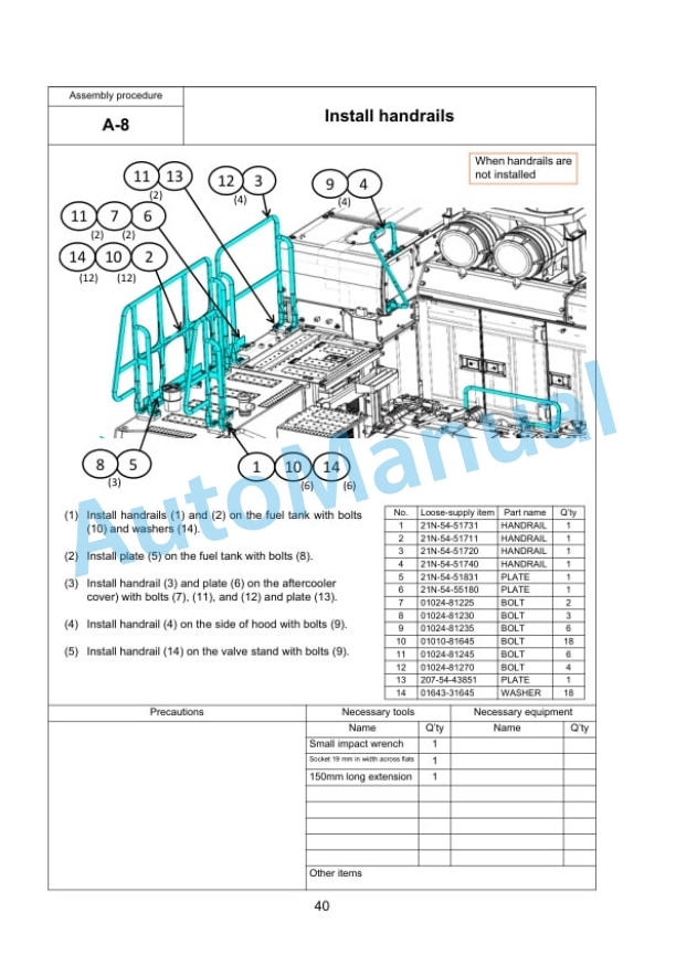
- 13.8. A8 Install handrails
- 13.9. A9 Install emergency stop switch on right front step (if equipped)
- 13.10. A10 Install precleaner
- 13.11. A11 Install swivel travel piping
- 13.12. A12 Install L.H. side step
- 13.13. A13 Install fixed ladder
- 13.14. A14 Install hydraulic stairway (if equipped)
- 13.15. A15Install flash light (if equipped)
- 13.16. A16 Install L.H. side step emergency stop switch (if equipped)
- 13.17. A17 Install KomVision camera
- 13.18. A18 Install counterweight
- 13.19. A19 Install counterweight revolving warning lamp (if quipped)
- 13.20. A20 Install counterweight rear lamp (if equipped)
- 13.21. A21 Install radiator cover
- 13.22. A22 Install exhaust tail pipe
- 13.23. A23 Change installed position of step light
- 13.24. A24 Change installed position of wireless LAN antenna
- 13.25. A25 Install operators cab revolving warning lamp (if equipped)
- 13.26. A26 Install operators cab handrail
- 13.27. A27 Install L.H. rearview mirror
- 13.28. A28 Install R.H. rearview mirror
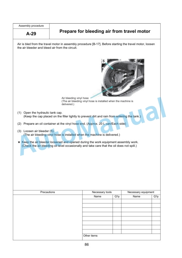
- 13.29. A29 Prepare for bleeding air from travel motor
- 13.30. A30 Bleed air from hydraulic pump section
- 13.31. A31 Tighten swing circle mounting bolts to specified torque
- 13.32. A32 Check and adjust track tension
- 13.33. A33 Check fuel, coolant and oil levels
- 13.34. A34 Parts to be touched up after field assembly
- 14. ASSEMBLING OF WORK EQUIPMENT OF BACKHOE
- 14.1. B1 Release remaining pressure in hydraulic circuit
- 14.2. B2 Install arm cylinder to boom
- 14.3. B3 Install arm cylinder hose
- 14.4. B4 Install boom cylinder to revolving frame
- 14.5. B5 Install boom cylinder hose
- 14.6. B6 Bleed air from cylinder
- 14.7. B7 Install boom foot dust seal
- 14.8. B8 Install boom assembly
- 14.9. B9 Install boom cylinder to boom assembly
- 14.10. B10 Install boom connection hoses (between chassis and boom assembly)
- 14.11. B11 Install arm assembly
- 14.12. B12 Install bucket cylinder hoses (between boom and bucket cylinder)
- 14.13. B13 Install bucket assembly
- 14.14. B14 Clearance standard for installation of work equipment
- 14.15. B15 Install work equipment grease piping
- 14.16. B16 Install work equipment lamps
- 14.17. B17 Grease after assembling work equipment
- 14.18. B18 Bleed air from swing motor
- 14.19. B19 Bleed air from travel motor
- 14.20. B20 Install travel motor guard
- 14.21. B21 Bleed air from hydraulic stairway (if equipped)
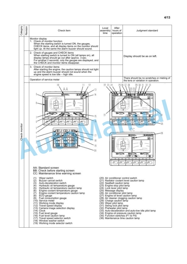
- 15. PROCEDURE FOR INSPECTION AND MAINTENANCE AFTER COMPLETION ASSEMBLY
- 15.1. M1 Replace return filter (Replace standard filter flushing filter)
- 15.2. M2 Flush hydraulic circuit
- 15.3. M3 Replace return filter (Replace flushing filter with standard filter)
- 15.4. M4 Replace pilot filter
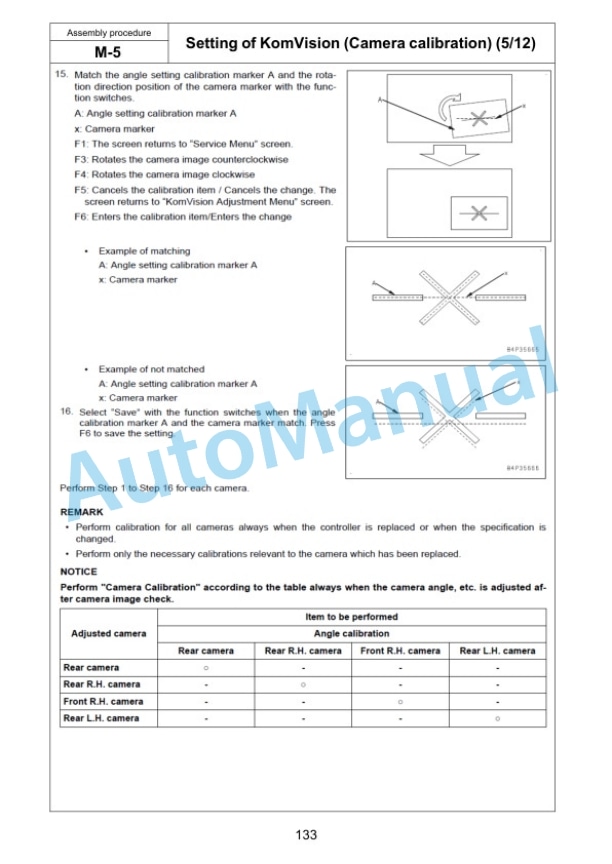
- 15.5. M5 Setting of KomVision (Camera calibration)
- 15.6. M6 Inspection method of 12 m visibility (KomVision)
- 15.7. M7 Method for starting up KOMTRAX terminal and default setting of KOMTRAX Plus controller
- 16. PROCEDURE FOR ASSEMBLING WORK EQUIPMENTOF LOADING SHOVEL
- 16.1. TRANSPORTATION POSTURE (ONLY WORK EQUIPMENT)
- 16.2. C 1 Release remaining pressure in hydraulic circuit
- 16.3. C 2 Bleed air from cylinder
- 16.4. C 3 Flush hydraulic circuit
- 16.5. C 4 Installation of Arm Cylinder Bottoms
- 16.6. C 5 Connection of Boom and Arm
- 16.7. C 6 Pulling out Boom Foot Pin and Boom Cylinder Foot Pin
- 16.8. C 7 Installation of Boom and Arm Assembly
- 16.9. C 8 Installation of Boom Hoses (Between Chassis and Boom)
- 16.10. C 9 Installation of Hoses Between Boom and Arm (Bottom Dump)
- 16.11. C10 Installation of Boom Cylinder Bottoms
- 16.12. C11 Installation of Boom Cylinder Hoses
- 16.13. C12 Installation of Boom Cylinder Head Pin
- 16.14. C13 Installation of Arm Cylinder Hoses
- 16.15. C14 Installation of Bucket Cylinder
- 16.16. C15 Installation of Bucket Cylinder Hoses
- 16.17. C16 Installation of Bucket Assembly
- 16.18. C17 Installation of Bottom Dump Cylinder Hoses
- 16.19. C18 Maintenance Standard
- 16.20. C19 Installation of Working Lamp
- 16.21. C20 Installation of Work Equipment Greasing Piping
- 16.22. C21 Checking Oil Level in Hydraulic Tank and Adding Oil
- 16.23. C22 Greasing After Assembling Work Equipment
- 17. Inspection of each part after assembly of loader
- 18. Field Assembly Inspection Report









There are no reviews yet.