

Description
-
Model List:
- PC2000-11 Hydraulic Excavator
- 1. Cover
- 2. GEN0027100MA4.pdf
- 2.1. FOREWORD
- 2.2. CONTENTS
- 2.3. SPECIFICATIONS
- 2.4. PRECAUTIONS FOR FIELD ASSEMBLY
- 2.5. DISPOSAL OF REMOVED PARTS
- 2.6. ASSEMBLY PROCEDURE, ASSEMBLY EQUIPMENT AND SCHEDULE
- 2.7. FLOWCHART OF MAIN ASSEMBLY PROCEDURE
- 2.8. KIT LAYOUT DIAGRAM
- 2.9. TRANSPORTATION POSTURES
- 2.10. LIST OF PARTS SENT INDIVIDUALLY
- 2.11. TOOLS AND EQUIPMENT TO BE USED FOR LOCAL ASSEMBLY
- 2.12. TIGHTENING TORQUE
- 2.13. COATING MATERIALS LIST
- 2.14. SELECTION OF WIRE ROPES USED FOR ASSEMBLY
- 2.15. SELECTION OF NYLON SLINGS USED FOR ASSEMBLY
- 2.16. ASSEMBLY OF CHASSIS
- 2.16.1.
- 2.16.2. A 1. Assembly of track frame assembly and center frame assembly
- 2.16.3. A 2. Installation of idler cushion cylinder piping
- 2.16.4. A 3. Installation of travel motor piping
- 2.16.5. A 4. Installation of travel motor cover
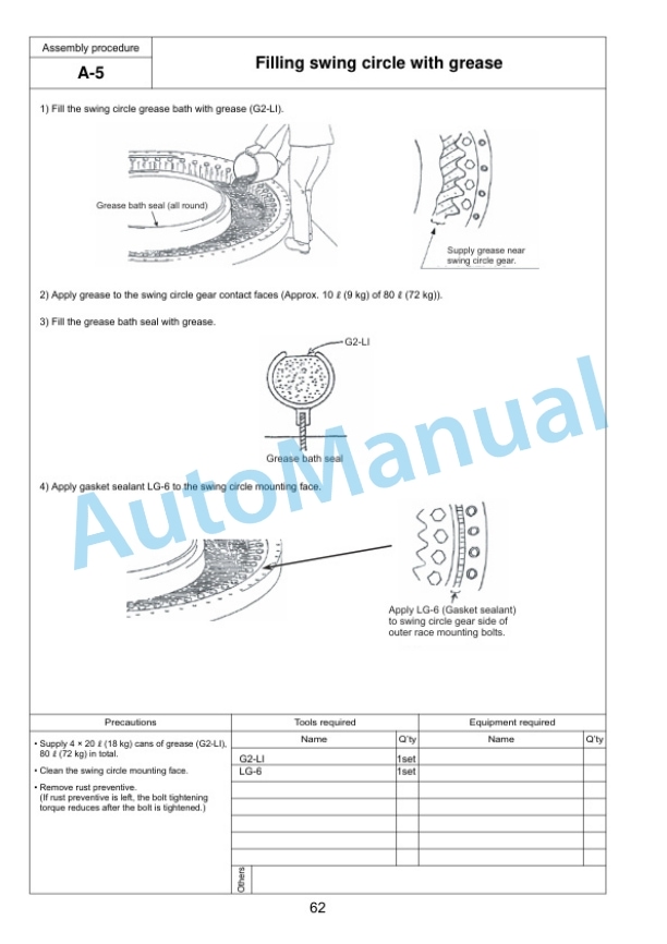
- 2.16.6. A 5. Filling swing circle with grease
- 2.16.7. A 6. Assembly of revolving frame assembly and undercarriage
- 2.16.8. A 7. Installation of swing machinery (front) assembly (27t) Installation of swing motor (front) assembly (32t)
- 2.16.9. A 8. Connection of swivel joint piping
- 2.16.10. A 9. Connection of swing circle grease piping
- 2.16.11.
- 2.16.12. A10. Installation of hydraulic tank assembly
- 2.16.13. A11. Installation of fuel tank assembly
- 2.16.14. A12. Connection of fuel tank assembly piping and wiring
- 2.16.15. A13. Installation of cab base assembly
- 2.16.16. A14. Installation of emergency escape ladder
- 2.16.17. A15. Installation of left floor assembly
- 2.16.18. A16. Connection of cab base assembly piping
- 2.16.19. A17. Connection of cab base assembly wiring
- 2.16.20. A18. Connection of left floor assembly heater piping
- 2.16.21.
- 2.16.22. A19. Connection of left floor assembly wiring
- 2.16.23. A20. Installation of tail pipe
- 2.16.24. A21. Installation of power module assembly
- 2.16.25. A22. Connection of suction piping
- 2.16.26. A23. Connection of oil cooler piping and pump drain piping
- 2.16.27. A24. Connection of fan motor drain piping
- 2.16.28. A25. Installation of suction unit undercover
- 2.16.29. A26. Connection of delivery piping
- 2.16.30. A27. Connection of pilot piping and fan motor piping
- 2.16.31. A28. Connection of power container assembly fuel piping
- 2.16.32. A29. Connection of power container assembly heater piping
- 2.16.33. A30. Connection of power container assembly wiring
- 2.16.34.
- 2.16.35. A31. Installation of operators cab assembly
- 2.16.36. A32. Installation of rotary lamp (if equipped)
- 2.16.37. A33 Installation of iridium antenna
- 2.16.38. A34. Connection of operators cab assembly wiring
- 2.16.39. A35. Connection of operators cab assembly hydraulic piping
- 2.16.40. A36. Connection of operators cab assembly window washer hose
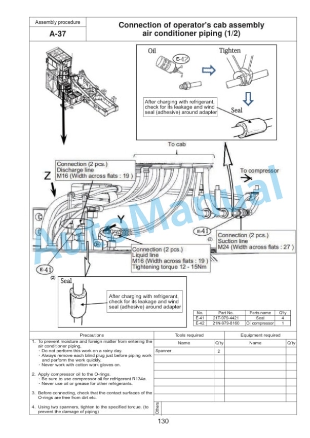
- 2.16.41. A37. Connection of operators cab assembly air conditioner piping
- 2.16.42. A38. Connection of operators cab assembly heater piping
- 2.16.43. A39. Installation of operators cab rear floor assembly
- 2.16.44. A40. Installation of handrail around operators cab
- 2.16.45.
- 2.16.46. A41. Installation of track frame ladder
- 2.16.47. A42. Installation of power module side catwalk assemblies (right and left)
- 2.16.48. A43. Installation of right floor assembly, grease can cover assembly and center floor
- 2.16.49. A44. Installation of fuel tank right catwalk assembly
- 2.16.50. A45. Installation of fuel tank front catwalk assembly
- 2.16.51. A46. Adjustment of exterior parts clearance
- 2.16.52. A47. Connection of grease reel piping
- 2.16.53. A48. Installation of access ladder assembly
- 2.16.54. A49. Installation of counterweight assembly
- 2.16.55. A50. Installation of deformation preventing stoppers for catwalk assemblies (left and right) on the side of power container
- 2.16.56. A51. Installation of handrail on counterweight
- 2.16.57. A52. Installation of handrail clamps
- 2.16.58. A53. Connection of fuel cut wire
- 2.16.59. A54. Connection of drain piping under power container
- 2.16.60. A55. Connection of battery wiring
- 2.16.61.
- 2.16.62. A56. Setting of hydraulic tank strainer
- 2.16.63. A57 Replacing standard filter to flushing filter
- 2.16.64. A58. Starting engine, checking oil and coolant levels, bleeding air from each part, and adjusting track
- 2.16.65. A59. Permanent tightening of swing circle bolt
- 2.16.66. A60. Parts to be touched up after field assembly (chassis side)
- 2.16.67. A61. Connection of engine heater connection port
- 2.16.68. A62. Installation of optional harness
- 2.16.69. A63. Installation of KomVision and rear lamp
- 2.16.70. A64. Connection of emergency stop switch (if equipped) (at the right below power module)
- 2.16.71. A65. Connection of emergency stop switch (if equipped) (at the left side of ladder)
- 2.16.72. A66. Installation of engine oil and PTO oil pipings
- 2.16.73. A67. Installation of coolant piping
- 2.16.74. A68. Installation of guard bracket (if equipped)
- 2.17. ASSEMBLY OF BACKHOE
- 2.17.1.
- 2.17.2. C 1. Installation of boom cylinder
- 2.17.3. C 2. Installation of boom cylinder hoses
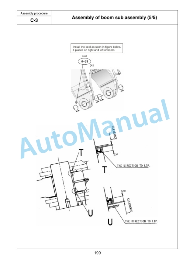
- 2.17.4. C 3. Assembly of boom sub assembly
- 2.17.5. C 4. Installation of boom assembly
- 2.17.6. C 5. Installation of boom cylinder head side
- 2.17.7. C 6. Installation of hoses between boom and chassis
- 2.17.8.
- 2.17.9. C 7. Installation of arm assembly
- 2.17.10. C 8. Installation of arm cylinder
- 2.17.11. C 9. Connection of hoses between boom and arm
- 2.17.12. C10. Connection of auto grease piping
- 2.17.13. C11. Connection of wiring between boom and chassis
- 2.17.14.
- 2.17.15. C12. Installation of bucket assembly
- 2.17.16. C13. Installation of bucket link
- 2.17.17. C14. Bleeding air from cylinders
- 2.17.18. C15. Parts to be touched up after field assembly (work equipment side)
- 2.17.19. C16. Bleeding air from auto grease circuit
- 2.18. LS. ASSEMBLY OF LOADING SHOVEL WORK EQUIPMENT
- 2.18.1. LS1 Installation of arm cylinder bottom parts
- 2.18.2. LS2 Installation of boom cylinder to machine body
- 2.18.3. LS3 Installation of boom cylinder hoses
- 2.18.4. LS4 Installation of boom cylinder piping
- 2.18.5. LS5 Installation of boom assembly
- 2.18.6. LS6 Installation of boom cylinder head pins
- 2.18.7. LS7 Installation of hose between machine body and boom
- 2.18.8. LS8 Installation of bucket cylinder assembly
- 2.18.9. LS9 Installation of arm assembly
- 2.18.10. LS10 Installation of arm cylinder assembly
- 2.18.11. LS11 Installation of hoses between boom and arm
- 2.18.12. LS12 Installation of bucket cylinder hoses
- 2.18.13. LS13 Installation of grease feed hose of bucket cylinder
- 2.18.14. LS14 Installation of bucket assembly
- 2.18.15. LS15 Installation of arm cylinder junction hoses
- 2.18.16. LS16 Installation of bottom dump hose and grease feed hose between arm and bucket
- 2.18.17. LS17 Installation of arm dump cushion (proximity switch)
- 2.19. INSPECTION AND SERVICING PROCEDURES AFTER ASSEMBLY
- 2.19.1. M 1. Inspection of oil levels and coolant levels and using standard of fuel and lubricant
- 2.19.2. M 2. Flushing of hydraulic circuit
- 2.19.3. M 3. Releasing residual pressure from hydraulic circuit
- 2.19.4. M 4. Releasing residual pressure from HIC circuit and check of gas pressure in HIC accumulator
- 2.19.5. M 5. Charging air conditioner with refrigerant
- 2.19.6. M 6. Installed angles of mirrors
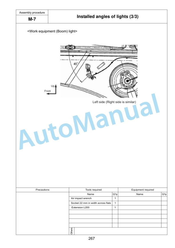
- 2.19.7. M 7. Installed angles of lights
- 2.19.8. M. Method for starting up KOMTRAX terminal and default setting of KOMTRAX Plus controller
- 2.19.9. M 9. Method of camera calibration for KomVision
- 2.20. PC200011 Main pump air bleeding check sheet
- 2.21. FIELD ASSEMBLY INSPECTION REPORT (BACKHOE)
- 2.22. FIELD ASSEMBLY INSPECTION REPORT (LOADING SHOVEL)











There are no reviews yet.