
Description
-
Model List:
- PC3000-6 Hydraulic Mining Shovel
- 1. INTRODUCTION
- 2. II. SAFETY
- 3. III. SPECIFICATIONS
- 4. MAIN ASSEMBLY GROUPS
- 4.1. General layout
- 4.2. Superstructure
- 4.3. Power House
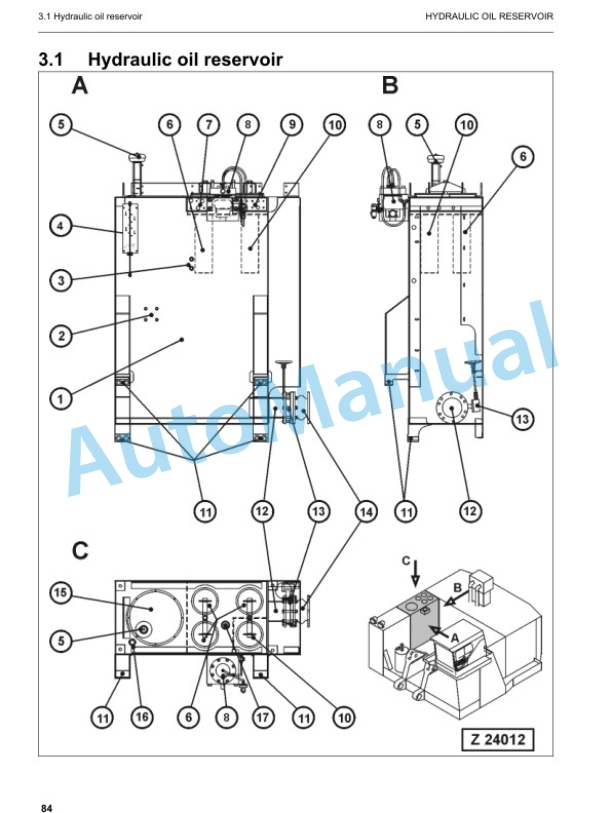
- 4.4. Hydraulic Oil Reservoir
- 4.5. Hydraulic Oil Cooler
- 4.6. Fuel tank (Fuel reservoir)
- 4.7. Counter weight
- 4.8. Cab support
- 4.9. Operators cab
- 4.10. Control blocks
- 4.11. Swing gears
- 4.12. Under carriage
- 5. DRIVE
- 5.1. Prime drive assembly
- 5.2. Engine and gearbox mount
- 5.3. Torque supports
- 5.4. Radiator fan Drive Assy.
- 5.5. Pump distributor gearbox (PTO)
- 5.5.1. Spline shaft housing
- 5.5.2. PTO lubrication and cooling
- 5.5.3. PTO valve adjustments
- 5.6. Coupling
- 5.7. Air Filter
- 6. HYDRAULIC OIL RESERVOIR
- 6.1. Hydraulic oil reservoir
- 6.2. Return and leak oil filter
- 6.3. Breather Filter
- 6.4. Location of electrical components
- 7. HYDRAULIC OIL COOLING
- 7.1. General
- 7.2. Hydraulic oil cooling circuit
- 7.3. Back pressure valve adjustment
- 7.4. Fan drive
- 7.4.1. Fan pump
- 7.4.2. Pressure relieve valve
- 7.4.3. Temperature relay
- 7.5. Cooler fan drive adjustment
- 8. CONTROLLING
- 8.1. Pilot pressure supply and adjustment
- 8.1.1. Pilot control arrangement
- 8.1.2. Pilot pressure adjustment
- 8.1.3. Check of Control Pressure
- 8.2. Slew brakes
- 8.3. Travel parking brake
- 8.4. Check of the pilot control logic
- 8.4.1. Check sheet FSA Page 1
- 8.4.2. Check sheet BHA Page 1
- 9. COMPONENTS
- 9.1. Main control block and valve arrangement
- 9.1.1. FSA arrangement
- 9.1.2. BHA arrangement
- 9.2. Distributor manifold
- 9.2.1. Front shovel attachment FSA
- 9.2.2. Back hoe attachment BHA
- 9.2.3. SRV with throttle check valve
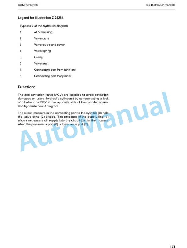
- 9.2.4. Anti cavitation valve (check valve)
- 9.3. Main control block
- 9.3.1. Load holding valve
- 9.3.2. High pressure filter
- 9.3.3. Pressure relieve valves and anticavitation valve
- 9.3.4. Pressure relieve valves and anticavitation valve
- 9.4. Compact valve blocks
- 9.5. Compact valve blocks
- 9.6. Auxiliary gear pumps
- 9.7. Hydraulic cylinder
- 9.8. Swing ring
- 10. MAIN HYDRAULIC PUMPS AND PUMP REGULATION
- 10.1. General
- 10.1.1. Pump location
- 10.2. Main pump operating principles
- 10.2.1. Main pump function
- 10.3. Main pump checks and adjustments
- 10.3.1. Peak point diesel engine test
- 10.3.2. Pressure transducer test
- 10.3.3. Cut off function
- 10.3.4. Pump regulation
- 10.3.5. Swing pump volume reduction
- 10.4. Electronic pump regulation
- 10.5. Pump Controller CR700
- 10.6. Multi Monitor
- 10.7. Multimonitor software instruction
- 10.7.1. Multimonitor main control
- 10.7.2. Service Menu screen
- 10.7.3. Monitoring (menu item 01)
- 10.7.4. Abnormality Record (menu item 02)
- 10.7.5. Default (menu item 03)
- 10.7.6. Adjustment (menu item 04)
- 10.7.7. Display Setup (menu item 05)
- 10.7.8. Table of fault messages and adjustments
- 10.8. Trouble shooting pump and pump regulation
- 11. OPERATING HYDRAULIC
- 11.1. General layout
- 11.2. Floating function of boom and stick only FSA
- 11.3. Check and Adjustments for MRVs and SRVs
- 11.3.1. Check and Adjustments for MRV
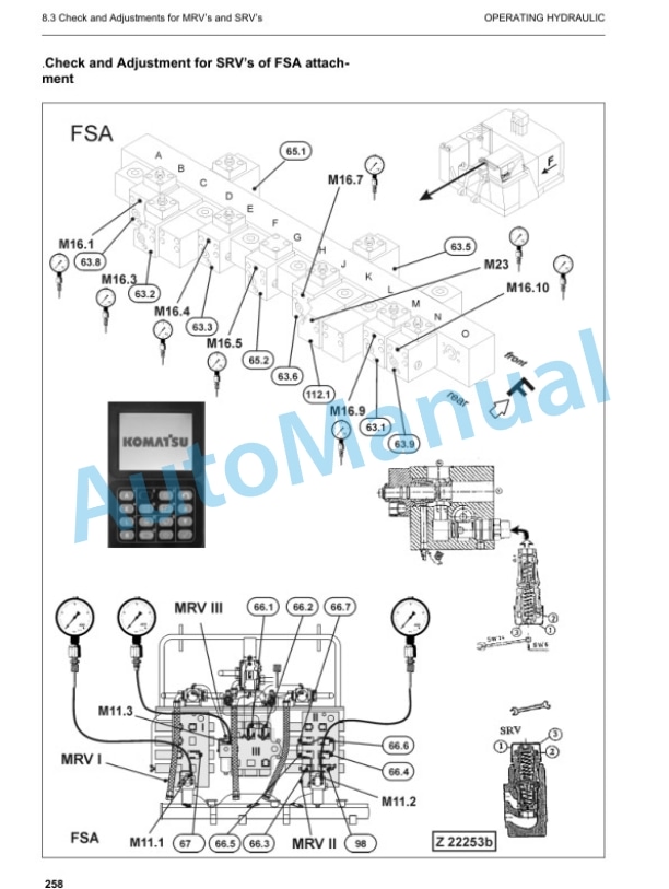
- 11.3.2. Check and Adjustment for SRVs
- 11.3.3. Check and adjustment of the throttle check valves
- 11.4. Hydraulic for the swing circuit
- 11.4.1. Hydraulic for the swing circuit
- 11.4.2. Slew gear box L S
- 11.4.3. Slew parking brake
- 11.4.4. Slew service brake valve
- 11.4.5. Checks and adjustment of the slew pressure valve
- 11.5. Travel circuit
- 11.5.1. Rotary joint
- 11.5.2. Travel motor A2FMt
- 11.5.3. Travel gear
- 11.5.4. Travel parking brake
- 11.5.5. Travel control function
- 11.5.6. Check and Adjustment SRV travel system
- 12. TRACK TENSION SYSTEM
- 12.1. General layout
- 12.2. Track tensioning function
- 12.2.1. Cushioning
- 12.2.2. Pressure Increasing valve PIV
- 12.3. Track tensioning adjustment
- 12.3.1. Track tensioning function check
- 13. ACCESS LADDER HYDRAULICALLY OPERATED
- 13.1. Access ladder
- 13.2. Access ladder functional description
- 14. CENTRAL REFILLING SYSTEM
- 14.1. Functional description
- 15. HINTS FOR READING THE HYDRAULIC CIRCUIT DIAGRAM
- 15.1. General
- 15.2. Symbolic
- 15.2.1. Lines, unions
- 15.2.2. Components, valves
- 15.2.3. Sensors
- 15.2.4. Valves, valve components
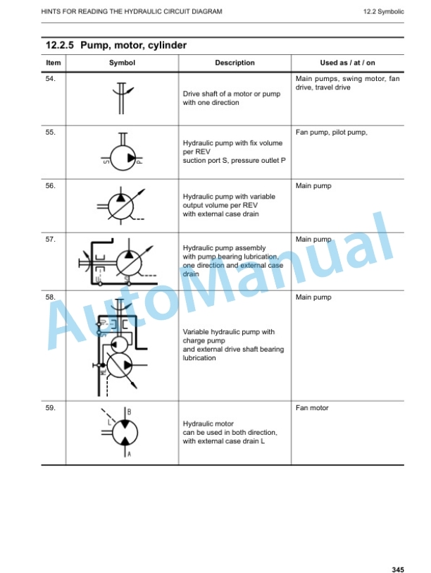
- 15.2.5. Pump, motor, cylinder
- 16. HINTS FOR READING THE ELECTRIC CIRCUIT DIAGRAM
- 16.1. Designation of electrical components
- 16.2. Electric symbols
- 16.3. Symbols
- 16.3.1. Drawing concept
- 16.3.2. Reading of the circuit diagram
- 17. ELECTRONIC TEXT MONITORING SYSTEM ETM
- 17.1. General Function
- 18. AUTOMATIC LUBRICATION SYSTEM
- 18.1. General Function
- 18.2. Function of a lubrication cycle
- 18.3. Lubrication pump drive
- 18.4. Lubrication pump
- 18.4.1. Adjustments lubricating pump speed
- 18.4.2. Adjustments lubricating pump pressure
- 18.5. Lubricant Injector (metering valve)
- 18.5.1. Connection of one or more injectors
- 18.5.2. Function lubrication injector (metering valve)
- 18.6. End line pressure switch
- 18.7. Lubricant in line filter
- 18.8. Lubricant level sensor
- 18.8.1. Capacitive digital type for machines with ETM
- 18.8.2. Capacitive analog type for machines with PLC
- 18.9. Lubrication system function and controlling
- 18.9.1. Central Lubrication System (CLS) function and controlling with ETM system (PC 3000)
- 18.9.2. Swing ring lubrication system (SLS) function and controlling with ETM system (PC3000)
- 18.10. Adjustment of the lubrication system with ETM
- 18.11. Trouble shooting lubricating system
- 18.11.1. Lubrication pump cylinder does not move
- 18.11.2. Lubricant pressure built up very slowly or not at all.
- 18.11.3. Insufficient lubricant supply to one or more attachment bearings
- 18.11.4. Insufficient lubricant at the swing ring gear


There are no reviews yet.