
Description
-
Model List:
- WA700-3 Wheel Loader
- 1. Cover
- 2. Drawings of removed units
- 3. Dimensions of removed units
- 4. Transportation of removed units
- 5. Assembly procedure, necessary equipment, and schedule
- 6. Layout of work space
- 7. Necessary tools and equipments
- 8. Assembly procedure
- 8.1. A0 Positioning front and rear axles and bare machine
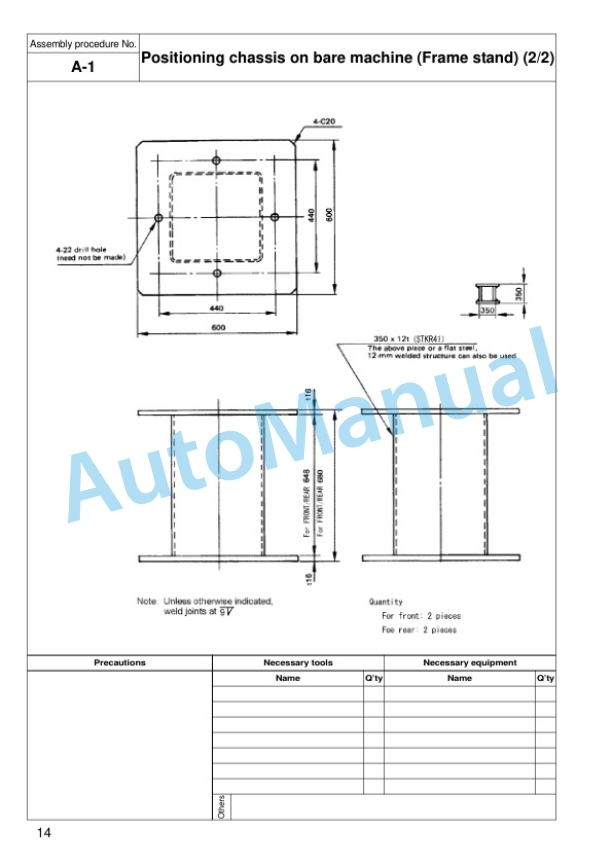
- 8.2. A1 Positioning chassis on bare machine (Frame stand)
- 8.3. A2 Installing rear axle
- 8.4. A3 Installing rear drive shaft
- 8.5. A4 Installing front axle assembly
- 8.6. A5 Installing front drive shaft
- 8.7. A6 Installing rear tires and wheel assembly
- 8.8. A7 Installing front tires and wheel assembly
- 8.9. A8 Installing bucket
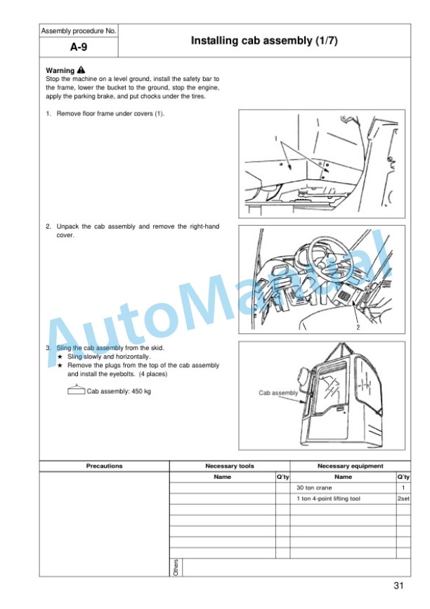
- 8.10. A9 Installing cab assembly
- 8.11. A10 Installing ROPS canopy assembly
- 8.12. A11 Installing front lamp assembly
- 8.13. A12 Installing floor handrail assembly (right)
- 8.14. A13 Installing muffler stack
- 8.15. A14 Installing counterweight
- 8.16. A15 Installing ladder assembly
- 8.17. A16 Installing front fender
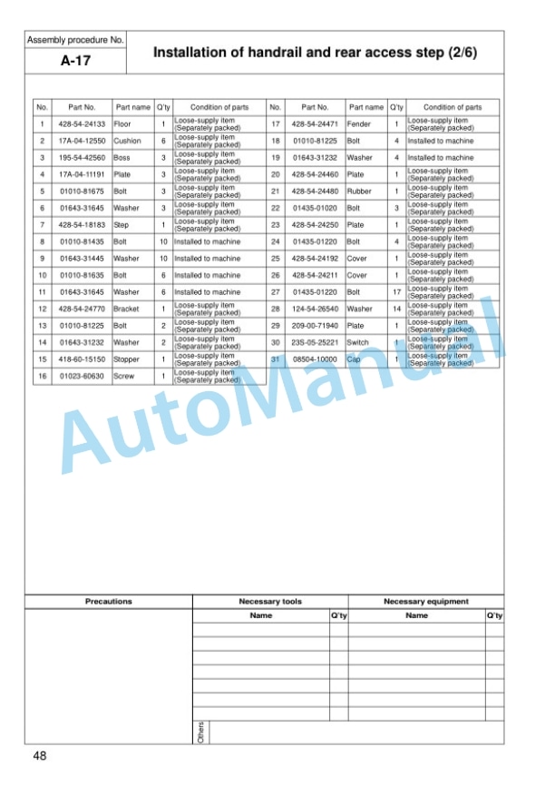
- 8.18. A17 Installation of handrail and rear access step
- 8.19. A18 Installing floor mat
- 8.20. A235 Calibration of AJSS lever angle and frame offset angle
- 8.21. A236 Calibration of AJSS lever angle and frame offset angle
- 8.22. A24 Stopper bolt adjustment (stop V)
- 8.23. A25 Without fire extinguisher, with only bracket
- 8.24. M1 Bleeding air from brake line
- 8.25. M2 Greasing work equipment and chassis
- 8.26. M3 Adjusting bucket positioner
- 8.27. M4 Adjusting boom kickout
- 8.28. M5 Inspection of all parts
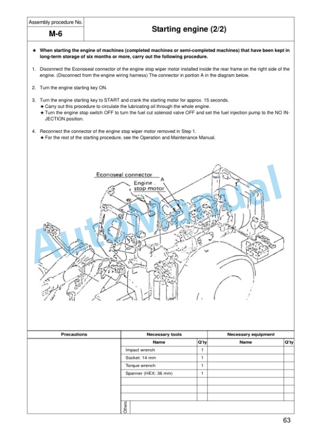
- 8.29. M6 Starting engine
- 8.30. M7 Bleeding air from piston pump
- 8.31. M8 Bleeding air from work equipment hydraulic circuit
- 8.32. M9 Check inflation pressure of tire
- 9. Appendix Field assembly inspection report



There are no reviews yet.