
Description
-
Model List:
- WA800-3E0 Wheel Loader
- WA900-3E0 Wheel Loader
- 1. COVER
- 2. CONTENTS
- 3. Dividing Process Overview (Major components alone)
- 4. Major Components Table of Dimensions
- 4.1. Land transportation
- 5. Work Space Layout
- 6. Schedule Table for Field Assembly
- 7. Facility, Jigs and Tools
- 7.1. Drawing of frame deck
- 7.2. Facilities used
- 8. List of Oil, Grease and Paints
- 9. Assembly procedure
- 9.1. No.0010 Oil, grease and coolant
- 9.2. No.0020 Oil, grease and coolant level
- 9.3. No.0030 Setting rear frame in place
- 9.4. No.0040 Setting front frame in place
- 9.5. No.0050 Joining front and rear frames
- 9.6. No.0060 Front and rear frames joining procedure
- 9.7. No.0070 Assembling the steering pin
- 9.8. No. 0080 Assembling the center drive shat
- 9.9. No. 0090 Connection of piping (Part 1)
- 9.10. No. 0100 Connection of piping (Part 2)
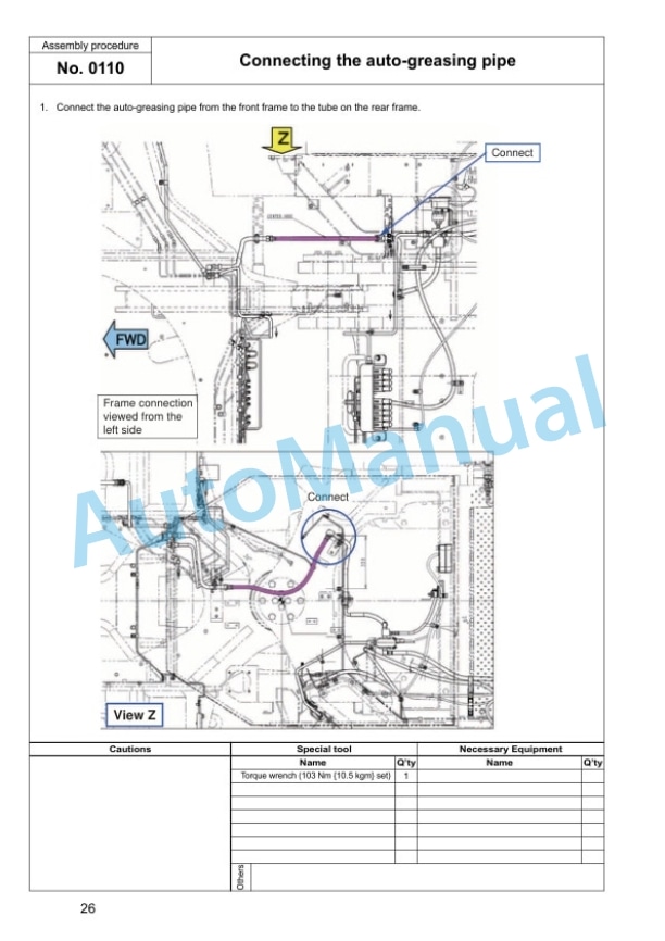
- 9.11. No. 0110 Connecting the autogreasing pipe
- 9.12. No. 0120 Setting the axle in place and assembling the support
- 9.13. No. 0130 Setting the bare machine in place
- 9.14. No. 0140 Assembling the rear axle
- 9.15. No. 0150 Rear axle rear side cover assembling procedure
- 9.16. No. 0160 Connecting the rear axle pipe
- 9.17. No. 0170 Assembling the rear drive shaft
- 9.18. No. 0180 Assembling the front axle
- 9.19. No. 0190 Connecting the front axle pipe
- 9.20. No. 0200 Connecting the front drive shat
- 9.21. No. 0210 Connecting the axle oil temperature sensor (For VHMS specification only)
- 9.22. No. 0220 Assembling the tires
- 9.23. No. 0230 Assembling the fuel tank
- 9.24. No. 0240 Fixing the drain pipe
- 9.25. No. 0250 Connecting the fuel pipe
- 9.26. No. 0260 Fixing the engine drain hoses
- 9.27. No. 0270 Assembling the hydraulic tank ladder
- 9.28. No. 0280 Assembling the floor and cab assembly
- 9.29. No. 0290 Connecting the air conditioner hose
- 9.30. No. 0300 Connecting the brake line
- 9.31. No. 0310 Connecting the window washer hose
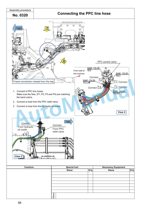
- 9.32. No. 0320 Connecting the PPC line hose
- 9.33. No.0330 Connecting the floor wiring harness
- 9.34. No. 0331 Connecting the floor wiring harness (Steering wheel specification If equipped)
- 9.35. No. 0333 Connection of floor wiring harness 1 (Riotinto specification If equipped)
- 9.36. No. 0334 Connection of floor wiring harness 2 (Riotinto specification If equipped)
- 9.37. No. 0335 Connecting the steering line (Steering wheel specification If equipped)
- 9.38. No. 0340 Connecting the link for AJSS (For AJSS specification only)
- 9.39. No. 0341 Connecting the link for AJSS (For AJSS specification only) 2
- 9.40. No. 0342 Connecting the link for AJSS (For AJSS specification only) 3
- 9.41. No. 0343 Connecting the link for AJSS (For AJSS specification only) 4
- 9.42. No. 0345 Calibration of the AJSS angle and frame offset angle
- 9.43. No. 0350 Assembling the autogreasing pump and connecting the pipe
- 9.44. No. 0360 Assembling the floor cover
- 9.45. No. 0370 Refilling the window washer
- 9.46. No. 0380 Assembling the battery box
- 9.47. No. 0390 Connecting and fixing the battery wiring
- 9.48. No. 0400 Assembling the battery step
- 9.49. No. 0430 Assembling the handrail (On the right hand battery box)
- 9.50. No. 0440 Assembling the rear access step
- 9.51. No. 0450 Assembling the left handrail (Part 1)
- 9.52. No. 0460 Assembling the left handrail (Part 2)
- 9.53. No. 0470 Assembling the rearview mirror
- 9.54. No. 0480 Assembling the exhaust pipe
- 9.55. No. 0490 Applying the counterweight antislip
- 9.56. No. 0500 Assembling the counterweight (WA9003E0 standard specification)
- 9.57. No. 0510 Assembling the counterweight (WA8003E0 Overseas general, optional specification and North American specification)
- 9.58. No. 0520 Assembling the counterweight (WA8003E0 Overseas general standard specification)
- 9.59. No. 0530 Assembling the front axle lamp and connecting the harness
- 9.60. No. 0540 Assembling the front lamp assembly
- 9.61. No. 0550 Assembling the ROPS canopy assembly
- 9.62. No. 0555 Assembling the yellow revolving lamp (yellow revolving lamp specification)
- 9.63. No. 0560 Assembling the antenna and work lamp
- 9.64. No. 0570 Assembling the VHMS antenna (For VHMS specification only)
- 9.65. No. 0580 Assembling the floor mat
- 9.66. No. 0590 Assembling the front fender
- 9.67. No. 0600 Engine starting procedure
- 9.68. No. 0610 Bleeding the brake air
- 9.69. No. 0620 Assembling the lift arm assembly (Part 1)
- 9.70. No. 0630 Assembling the lift arm assembly (Part 2)
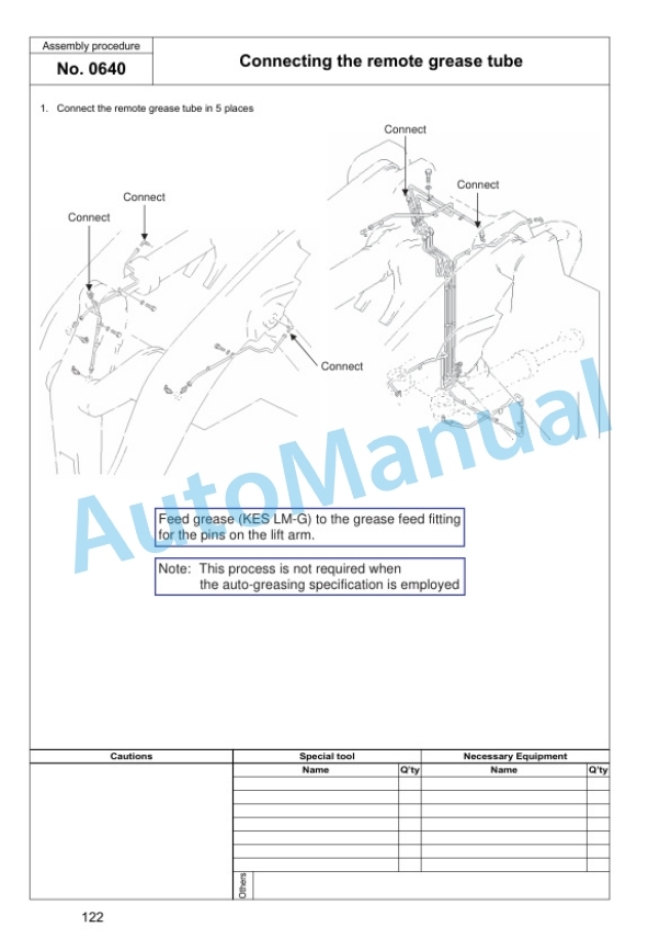
- 9.71. No. 0640 Connecting the remote grease tube
- 9.72. No. 0650 Assembling the bucket (Part 1)
- 9.73. No. 0660 Assembling the bucket (Part 2)
- 9.74. No. 0670 Assembling the bucket (Part 3)
- 9.75. No. 0680 Assembling the cover (Bottom of the counterweight)
- 9.76. No. 0690 Feeding the grease
- 9.77. No. 0700 Work equipment hydraulic circuit air bleeding procedure
- 9.78. No. 0710 Adjusting the bucket positioner
- 9.79. No. 0720 Adjusting the new 2 stage (Overseas general standard)
- 9.80. No. 0730 Adjusting the new 2 stage (North American standard specification)
- 9.81. No. 0740 Assembling the lift arm angle sensor
- 9.82. No. 0750 Adjusting the active working system and boom kickout switch (Overseas general standard and domestic standard)
- 9.83. No. 0760 Touchup work
- 9.84. No. 0770 Applying the decal (For the overseasdirected products only)
- 10. Machine check sheet for field assembly









There are no reviews yet.