
Description
-
Model List:
- WD600-6R Wheel Dozer
- 1. Block outline (for principal components only)
- 2. Principal component dimension table
- 3. Work space layout
- 4. General assembly schedule
- 5. List of equipment, jigs, tools and consumables
- 6. Oil, grease and paints
- 7. Assembly procedure
- 7.1. Oil and coolant
- 7.2. Oil and coolant capacity
- 7.3. Setting the front axle and bare machine to stationary position
- 7.4. Installing the front axle
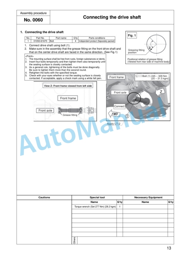
- 7.5. Connecting the drive shaft
- 7.6. Connecting the brake pipe
- 7.7. Connecting the brake pipe (Brake cooling specification)
- 7.8. Installing tire and rim assembly
- 7.9. Installing step
- 7.10. Installing cab (1)
- 7.11. Installing cab (2) (AJSS specification)
- 7.12. Installing cab (2) (Steering wheel specification)
- 7.13. Installing cab (2) (AJSS and steering wheel specification)
- 7.14. Installing cab (3)
- 7.15. Installing cab (4) (AJSS specification)
- 7.16. Installing cab (4) (Steering wheel specification)
- 7.17. Installing cab (5) (Steering wheel specification)
- 7.18. Installing cab (6) (AJSS and steering wheel specification)
- 7.19. Installing cab harness (1/3)
- 7.20. Installing cab harness (2/3)
- 7.21. Installing cab harness (3/3) (Steering wheel specification)
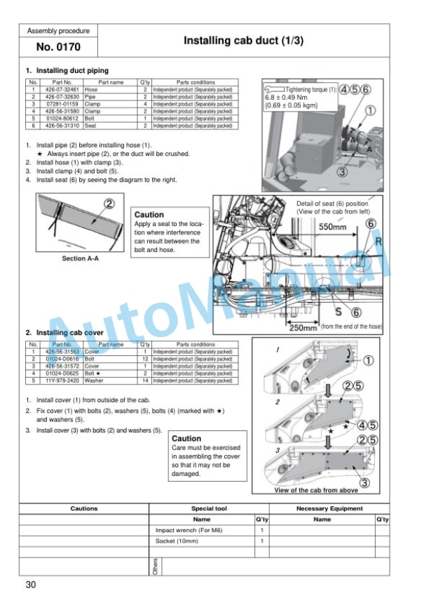
- 7.22. Installing cab duct (1/3)
- 7.23. Installing cab duct (2/3)
- 7.24. Installing cab duct (3/3)
- 7.25. Installation of yellow rotary lamp
- 7.26. Installing front fender
- 7.27. Installing front light support and connection
- 7.28. Installing muffler stack and mirror
- 7.29. Installing rear access ladder and L.H. platform
- 7.30. Installing the left handrail
- 7.31. Installing right platform and R.H. handrail
- 7.32. Installing fire extinguisher
- 7.33. Installing the rear fender mudguard plate
- 7.34. Installing rear fender
- 7.35. Installing cab undercover
- 7.36. Checking of sections
- 7.37. Air bleeding of work equipment hydraulic circuit and respective cylinders
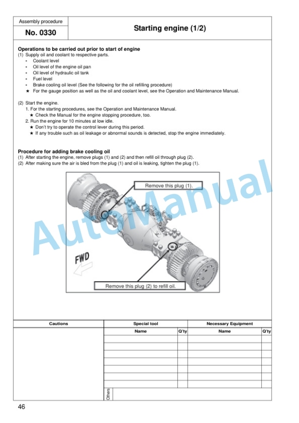
- 7.38. Starting engine (1/2)
- 7.39. Starting engine (2/2)
- 7.40. Bleeding air from brake system
- 7.41. Installation of Hlink and Ylink
- 7.42. Installation of right and left support assemblies
- 7.43. Installation of right and left frame assemblies
- 7.44. Installation of blade assembly (1/2)
- 7.45. Installation of blade assembly (2/2)
- 7.46. Work equipment greasing (1st time)
- 7.47. Setting machine monitor
- 7.48. Work equipment calibration1, Outline and selection of service mode
- 7.49. Work equipment calibration2, Display of service mode (reference)
- 7.50. Work equipment calibration3, Work equipment EPC starting point correction1 (LOWER)
- 7.51. Work equipment calibration4, Work equipment EPC starting point correction2 (RAISE)
- 7.52. Work equipment calibration5, Work equipment control lever detent position correction
- 7.53. Work equipment calibration6, Pitching flow correction
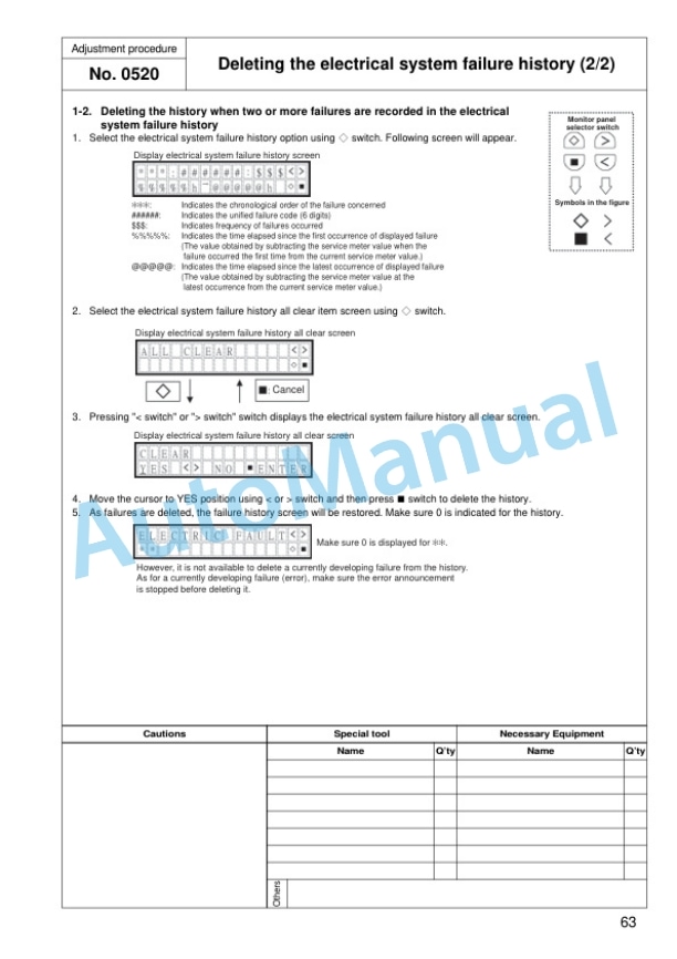
- 7.54. Deleting the electrical system failure history (1/2)
- 7.55. Deleting the electrical system failure history (2/2)
- 7.56. Installing the floor mat (AJSS specification)
- 7.57. Installing the floor mat (Steering wheel specification)
- 7.58. Runningin procedure (1/2)
- 7.59. Runningin procedure (2/2)
- 7.60. Greasing (2nd time)
- 7.61. Touch up work
- 7.62. On use of starter kit (dummy harness) and precaution on its use
- 7.63. Starter kit (dummy harness) assembling procedure
- 7.64. Check inflation pressure of tires
- 8. Appendix Machine check sheet for field assembly


There are no reviews yet.