Home » Yanmar 2TNV70 to 4TNV106T Application Manual
Yanmar 2TNV70 to 4TNV106T Application Manual $ 20.00
Type Of Manual: Application Manual
Number of Pages: 235
Size: 13.4MB
Format: PDF
Description
Model List:
2TNV70, 3TNV70, 3TNV76, 3TNV82A, 3TNV82A-B, 3TNV84, 3TNV84T, 3TNV84T-B, 3TNV88, 3TNV88-B, 3TNV88-U, 4TNV84, 4TNV84T, 4TNV84T-Z, 4TNV88, 4TNV88-B, 4TNV88-U, 4TNV94L, 4TNV98, 4TNV98-Z, 4TNV98-E, 4TNV98T, 4TNV98T-Z, 4TNV106, 4TNV106T
1. Application Standard
1.1. Application Standard
1.2. Special Operating Environment
1.2.1. Precautions Against Dusty Conditions
1.2.2. Precautions for Outdoor Installation
1.2.3. Precautions Against Salty Conditions (Air, Sea Water, Road Salt)
1.2.4. Precautions Against Cold Environment
1.2.5. Precautions Against Hot Environment
1.3. Low-temperature startability
1.3.1. Combination of Starting Devices for Each Driven Machine
1.3.1.1. IDI Series
1.3.1.2. DI Series
1.3.2. Allowable Air Intake Restriction and Exhaust Back Pressures
1.3.2.1. Allowable Air Intake Restriction
1.3.2.2. Allowable Exhaust Back Pressure
1.3.2.3. The Necessity of Intake/Exhaust Pressure Settings for Engine with EGR
1.3.2.4. The characteristics of Intake/Exhaust Pressure for the engine with EGR
1.3.2.5. The Intake/Exhaust Pressure is changed because of changing the open level of EGR depending on the load rate for the engine with EGR. See Figure 1-2 below as the example. It is also changed depending on the engine rated speed.
1.3.2.6. Note point at the Intake/Exhaust Pressure Settings for the engine with EGR
1.3.2.7. NV84T-Z Allowable Intake/Exhaust Pressure Settings (at rated output)
1.3.2.8. NV98-Z Allowable Intake/Exhaust Pressure Settings (at rated output)
1.3.2.9. NV98-E/Z Allowable Intake/Exhaust Pressure Settings (at rated output)
1.3.2.10. NV98T-Z Allowable Intake/Exhaust Pressure Settings (at rated output)
1.3.2.11. NV98T-Z Allowable Intake/Exhaust Pressure Settings (at rated output)
1.3.3. EPA Emission Control Regulations for Non-road Diesel Engine (Requirements for the Driven Machine Manufacturers)
1.3.4. Engine Output
1.3.5. Emission Control Label
1.3.6. Fuel Inlet Label
1.3.7. Installation Evaluation
1.3.8. Engine Maintenance
1.3.9. Tamper Resistance
1.3.10. Report on Sales in the USA
1.3.11. Recall – EPA
2. Engine Model Selection
2.1. Model Designation
2.2. Engine Classification
2.2.1. Classification with Injection System
2.2.2. Classification with Displacement
2.2.3. Classification with Engine Speed
2.2.4. Engine Classification with Above Mentioned Conditions
2.3. Standard Engines for Driven Machines
2.3.1. Classification of Standard Engines for Driven Machines
2.3.1.1. Engine Model Nomenclature
2.3.1.2. Model Name of Engine by Driven Machines and Category
2.3.2. Specifications of Standard Engines for Driven Machines
2.3.2.1. Machine standard engine (NV1 to complies with EPA Tier4)
2.3.2.2. Machine standard engine (NV2 to complies with EPA Tier2)
2.3.2.3. Machine standard engine (NV2 to complies with EPA Interim Tier4)
2.3.2.4. Machine standard engine (NV3 to complies with EPA Tier2)
2.3.2.5. Machine standard engine (NV3 to complies with EPA Interim Tier4, Tier3)
3. Specifications
3.1. Atmospheric Conditions and Engine Configuration Affect Engine Output
3.1.1. Engine Output for Industrial Use
3.1.2. Engine Output for Generator Use
3.2. Specifications
3.2.1. IDI Series
3.2.1.1. NV70 (complies with EPA Tier4)
3.2.1.2. NV70 (complies with EPA Tier4)
3.2.1.3. NV76 (complies with EPA Tier4)
3.2.2. DI Series
3.2.2.1. NV82A (complies with EPA Tier2)
3.2.2.2. NV82A-B/-Z (complies with EPA Interim Tier4)
3.2.2.3. NV82A-B 3TNV82A-Z (Electronically controlled)
3.2.2.4. NV84 (complies with EPA Tier2)
3.2.2.5. NV84T-Z (Electronically controlled)
3.2.2.6. NV88 (complies with EPA Tier2)
3.2.2.7. NV88-U/-E (complies with EPA Interim Tier4)
3.2.2.8. NV88-U 3TNV88-E (Electronically controlled)
3.2.2.9. NV88-B/-Z (complies with EPA Interim Tier4)
3.2.2.10. NV88-B 3TNV88-Z (Electronically controlled)
3.2.2.11. NV84T (complies with EPA Tier2)
3.2.2.12. NV84T-B (complies with EPA Interim Tier4)
3.2.2.13. NV84 (complies with EPA Tier2)
3.2.2.14. NV88 (complies with EPA Tier2)
3.2.2.15. NV88-U/-E (complies with EPA Interim Tier4)
3.2.2.16. NV88-U 4TNV88-E (Electronically controlled)
3.2.2.17. NV88-B/-Z (complies with EPA Interim Tier4)
3.2.2.18. NV88-B 4TNV88-Z (Electronically controlled)
3.2.2.19. NV84T (complies with EPA Tier2)
3.2.2.20. NV84T-Z/-B (complies with EPA Interim Tier4)
3.2.2.21. NV84T-Z
3.2.2.22. NV94L (complies with EPA Tier2)
3.2.2.23. NV98 (complies with EPA Tier2)
3.2.2.24. NV98-E (complies with EPA Interim Tier4)
3.2.2.25. NV98-E
3.2.2.26. NV98-Z (complies with EPA Interim Tier4)
3.2.2.27. NV98-Z
3.2.2.28. NV98T (complies with EPA Tier2)
3.2.2.29. NV98T-Z (complies with EPA Tier3)
3.2.2.30. NV98T-Z
3.3. Dimensions
3.3.1. IDI Series
3.3.2. DI Series
3.3.2.1. NV82A/3TNV82A-B
3.3.2.2. NV82A-B 3TNV82A-Z (Electronically controlled)
3.3.2.3. NV84/3TNV88/3TNV88-U/3TNV88-B
3.3.2.4. NV88-U/3TNV88-B 3TNV88-E/3TNV88-Z (Electronically controlled)
3.3.2.5. NV84T-B
3.3.2.6. NV84T
3.3.2.7. NV84T-Z
3.3.2.8. NV84T-Z
3.3.2.9. NV84/4TNV88/4TNV88-U/4TNV88-B
3.3.2.10. NV88-U/4TNV88-B 4TNV88-E/4TNV88-Z (Electronically controlled)
3.3.2.11. NV84T-Z
3.3.2.12. NV84T-Z
3.3.2.13. NV84T
3.3.2.14. NV94L/4TNV98
3.3.2.15. NV98-E/4TNV98-Z
3.3.2.16. NV98-E/4TNV98-Z
3.3.2.17. NV98T-Z
3.3.2.18. NV98T-Z (Conforming to EPA Tier 3 Standards)
3.3.2.19. NV98T
4. Correcting Observed Power
4.1. Power Corrections
4.1.1. Correction Formula (A)
4.1.2. Correction Formula (B)
4.1.3. Corrections for Reducing Exhaust Smoke Density at Altitude
4.2. Atmospheric Pressure Calculation for Change in Altitude
4.3. Atmospheric Temperature Calculation for Change in Altitude
4.4. Relationships among Altitude, Atmospheric Pressure and Atmospheric Temperature
4.5. How to Obtain Relative Humidity by Dry and Wet-Bulb Thermometer
4.6. Relationship between Atmospheric Temperature and Saturation Vapor Pressure
4.7. Altitude Characteristics
4.7.1. Reduction of Output
4.7.2. Reduction of Torque-rise (Reduction of Maximum Torque)
4.7.3. Startability at Each Altitude
4.7.4. Exhaust White Smoke
4.7.5. Misfire at High Altitude
5. Engine Performance
5.1. Performance Curves
5.1.1. Output Curve P
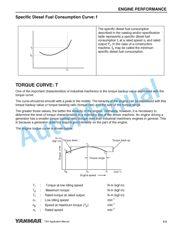
5.1.2. Specific Diesel Fuel Consumption Curve f
5.2. Torque Curve T
5.3. Partial Recovery Ratio
5.4. Governor Performance
5.4.1. Governor Performance of TNV Series Engines
6. Cold Starting Aids
6.1. Glow Plug
6.1.1. Glow Plug Structure
6.1.2. Control Circuit Diagram for Standard Glow Plug
6.1.3. Control Circuit Parts for Glow Plug
6.1.3.1. Pattern of Key Switch Terminal Yanmar Part No. 129115 – 91250
6.1.3.2. Timer and Preheat Indicator
6.1.3.3. Relay for Starting Aids (Power Relay)
6.1.4. Control Circuit Diagram for On-Glow (Mechanical Governor)
6.1.4.1. Controller (IDI)
6.1.4.2. Controller (IDI)
6.1.4.3. Power Relay
6.1.4.4. Engine Coolant Temperature Switch
6.1.5. Control Circuit Diagram for On-Glow (Eco Governor)
6.1.5.1. After-Heat (Eco Governor Option)
6.2. Inlet Air Heater
6.2.1. Inlet Air Heater Structure
6.2.2. Control Circuit Diagram for Standard Inlet Air Heater
6.2.3. Inlet Air Heater Capacity and Power Relay
6.2.4. Control Circuit for Specific Driven Machine Applications
6.2.5. Inlet Air Heater Control Circuit Components
6.2.5.1. Key Switch Terminal Pattern
6.2.5.2. Timer and Preheat Indicator
6.2.6. After-Heat (Eco Governor Option)
6.2.6.1. Relay for Starting Aids
6.2.7. Control Circuit Diagram for On-Glow (Eco Governor)
6.2.7.1. After-Heat (Eco Governor Option)
6.2.7.2. Relay for Starting Aids
6.3. Engine Block Heater
6.3.1. Block Heater Configuration
6.3.2. Block Heater Connection Diagram
6.4. Cold Start Device (CSD) for MP Pump
6.4.1. Features of CSD
6.4.2. Confirmation of Safety at Cold Start
7. Air Intake System
7.1. Air Capacity Required for Combustion
7.1.1. Calculation of the Air Capacity
7.1.1.1. Air Capacity Required for Combustion
7.1.1.2. Apparent Air Capacity
7.1.2. Air Cleaner Selection Table
7.2. Air Cleaner
7.2.1. Dust Removing Principle of the Air Cleaner
7.2.2. Structure of Air Cleaner
7.2.2.1. Types of Air Cleaner Element
7.2.2.2. Structure of Single Element Type
7.2.2.3. Structure of Double Element Type
7.2.3. Dust Indicator
7.2.3.1. Mechanical Dust Indicator Part Code 126650-12680
7.2.3.2. Electric Dust Indicator Part Code 119140-12680
7.2.4. Air Cleaner Installation
7.2.5. Air Intake System Hose Routing
7.2.5.1. Intake Port Position
7.3. Air Intake Restriction
7.3.1. Measurement of Air Intake Restriction
7.3.2. Allowable Air Intake Restriction
8. Exhaust System
8.1. In-Use Testing Requirements
8.2. EGR Equipment
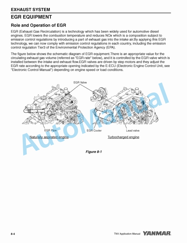
8.2.1. Role and Operation of EGR
8.2.2. Structure of Each Device
8.2.2.1. EGR Valve
8.2.2.2. EGR Cooler
8.2.2.3. Lead Valve
8.3. Intake/Exhaust Pressure
8.4. Turbocharger
8.4.1. Structure of Turbocharger
8.4.2. Handling the Turbocharger
8.5. Exhaust Back Pressure
8.5.1. Allowable Exhaust Back Pressure
8.6. Exhaust Muffler
8.7. Fitting Precautions for Exhaust System
8.7.1. Installation of Exhaust Muffler
8.7.2. Routing of Exhaust System Components
8.8. Exhaust Gas Volume and Exhaust Back Pressure
8.8.1. Exhaust Gas Volume
8.8.1.1. Combustion Gas Volume
8.8.1.2. Exhaust Gas Volume
8.8.1.3. Exhaust Back Pressure
8.8.2. Total Back Pressure of Exhaust System P
8.8.3. Materials for Calculating Exhaust Back Pressure
8.9. Black Smoke Exhaust
8.9.1. Characteristic Factors of Black Smoke Generation
8.9.2. Measurement of Smoke Density
9. Cooling System
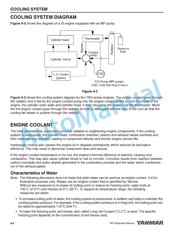
9.1. Cooling System Diagram
9.2. Engine Coolant
9.2.1. Characteristics of Water
9.2.2. Water Quality Needed to Prepare Engine Coolant
9.2.3. Required Engine Coolant Characteristics
9.2.4. Typical Properties of LLC (Yanmar Standard)
9.3. Radiator
9.3.1. Example of the structure of a radiator made from aluminum
9.3.2. Radiator Selection
9.3.3. Radiator Position
9.3.3.1. Pusher Fan
9.3.3.2. Puller Fan
9.3.4. Radiator Standard Capacity
9.3.5. Precautions for Installation
9.3.5.1. Installation example of an aluminum radiator with resin tank
9.3.5.2. Notes on installation
9.3.5.3. Other Precautions
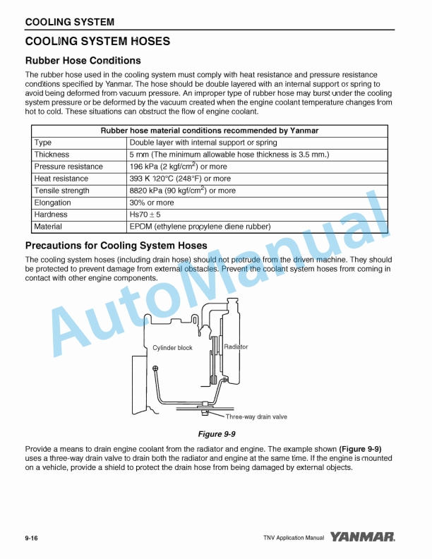
9.4. Cooling System Hoses
9.4.1. Rubber Hose Conditions
9.4.2. Precautions for Cooling System Hoses
9.4.3. Hose Clamps
9.4.4. Supplying Engine Coolant
9.5. Thermostat
9.5.1. Operation of Thermostat and Flow of Coolant
9.5.1.1. Under cold conditions
9.5.1.2. Under warm conditions
9.6. Engine Coolant Temperature Switch
9.6.1. Example of wiring diagram
9.7. Cooling System Recovery Tank
9.7.1. Radiator Cap Structure
9.7.2. Function of Cooling System Recovery Tank
9.7.3. Selection of Engine Coolant Recovery Tank Capacity
9.7.4. Installation of Engine Coolant Recovery Tank
9.8. Heat Rejection to Engine Coolant
9.8.1. Calculation of Heat Rejection to Engine Coolant
9.8.2. Discharge Engine Coolant Flow from Engine Coolant Pump
9.9. Cooling Fan and Its Drive System
9.9.1. Cooling Fan
9.9.1.1. Selection of Cooling Fan
9.9.1.2. Pusher Fan / Puller Fan
9.9.1.3. Material and Deformation of the Cooling Fan
9.9.1.4. Fan Spacer
9.9.1.5. V-pulley
10. Diesel Fuel System
10.1. Fuel Inlet Label
10.2. Diesel Fuel System Diagram
10.2.1. Fuel System (IDI Engine/Equipped with Mechanical Fuel Feed Pump)
10.2.2. Fuel System (IDI Engine/Equipped with Electric Fuel Feed Pump)
10.2.3. Fuel System (DI Engine/Equipped with Electric Fuel Feed Pump)
10.3. Standard Diesel Fuel Line Layout
10.3.1. Layout for IDI Engines with ML Type Diesel Fuel Injection Pump
10.3.1.1. Diesel Fuel Line Layout for IDI Engines
10.3.1.2. Diesel Fuel System Part Names and Functions for IDI Engines
10.3.1.3. Layout Dimension for IDI Engines
10.3.1.4. Parts Specification for IDI Engines
10.3.1.5. Fuel Filter for IDI Engines
10.3.2. Layout for DI Engines with MP2 or MP4 Type Fuel Injection Pump
10.3.2.1. Fuel Line Layout for DI Engines.
10.3.2.2. Diesel Fuel System Part Names and Functions for DI Engines
10.3.2.3. Fuel Line Layout (DI engines)
10.3.2.4. Parts Specification for Engine
10.3.2.5. For poor quality fuel
10.4. Diesel Fuel
10.4.1. Recommended Diesel Fuel
10.4.2. Fuels for Diesel Engines
10.4.2.1. Classifications of Mineral Oil
10.4.2.2. Fundamental Requirements for Diesel Fuel
10.4.2.3. Properties of Diesel Fuel
10.4.3. Selection of Diesel Fuel
10.4.3.1. Volatile Matter
10.4.3.2. Impurities
10.4.3.3. Use Diesel Fuels Classified According to Ambient Temperature
10.4.4. Engine Trouble Caused by Improper Diesel Fuel
10.4.4.1. Deposits on the Exhaust Valve
10.4.4.2. Deposits on the Piston Ring Grooves
10.4.4.3. Clogging or Corrosion of the Injection Hole of the Fuel Injection Valve
10.4.4.4. Sediments Inside the Crankcase
10.4.5. Diesel Fuel Properties and Engine Performance
10.4.5.1. Deposits in Combustion Chamber
10.4.5.2. Startability



There are no reviews yet.