
Description
-
Model List:
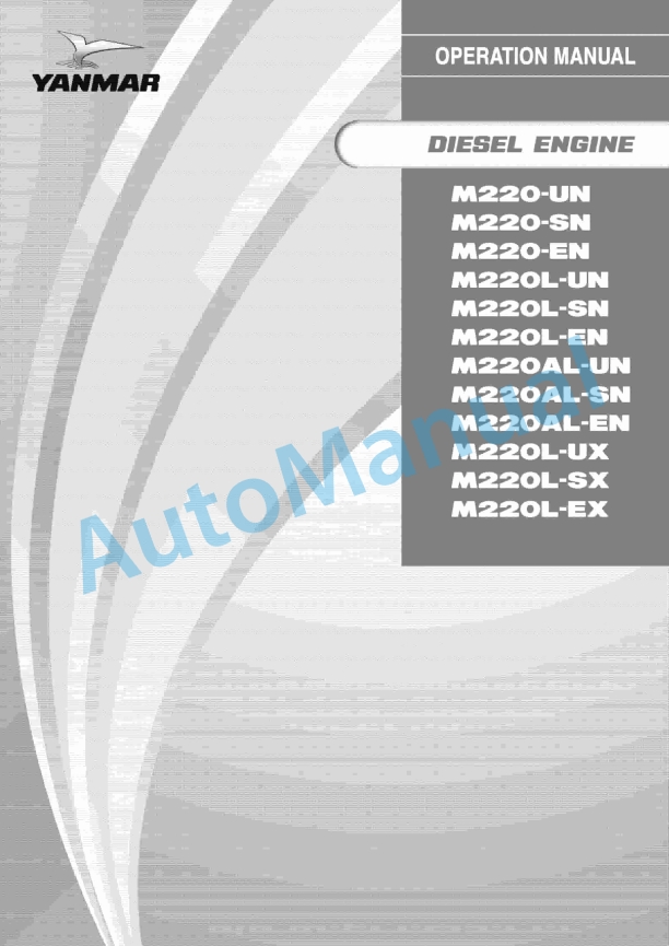
- M220-UN, M220-SN, M220-EN, M220L-UN, M220L-SN, M220L-EN, M220AL-UN, M220AL-SN, M220AL-EN, M220L-UX, M220L-SX, M220L-EX Diesel Engine
- 1. CONTENTS
- 2. PREFACE
- 2.1. OUTLINE
- 2.2. PRECATIONS ON SAFETY
- 2.2.1. Basic Precation
- 2.3. PRECATIONS ON OPERATION
- 2.3.1. Prior to Starting of the Engine
- 2.3.2. When Starting the Engine
- 2.3.3. When Stopping the Engine
- 2.4. PRECATIONS ON MAINTENANCE
- 2.4.1. Precations Prior to Maintenance Servicing
- 2.4.2. Precations during Maintenance Servicing
- 2.4.3. Precations at Coplection of Maintenance Servicing
- 2.5. LIST OF SAFETY LABELS
- 3. ENGINE DESCRIPTION
- 3.1. Marine Main Engine
- 3.2. Marine Auxiliary Engine/Land Engine
- 4. ESSENTIAL CHECK POINTS (General Instructions)
- 5. TABLE OF ENGINE STANDARD ADJUSTMENTS
- 6. OPERATION
- 6.1. Operational Preparation
- 6.2. Starting
- 6.3. Warming-up
- 6.4. Initial Running
- 6.5. Loard Running
- 6.6. Stopping
- 6.7. Operation Cutting Off a Fuel Injection Pump
- 7. FUEL OIL / LUB. OIL COOLIMG WATER
- 7.1. Fuel Oil
- 7.2. Lubricating Oil
- 7.3. Guide for Lub. Oil Changing Time
- 7.4. Cooling Water
- 8. PERIODICAL CHECKING
- 8.1. Perodical Checking (for Normal Service Engine)
- 8.2. Periodical Checking (for Emergency Engine)
- 9. DISMAINTLING REASSEMBLING ADJUSTMENT
- 9.1. Dismaintling Reassembly of Cylinder Head Its Accessories
- 9.1.1. Cylinder head
- 9.1.2. Suction exhaust valves
- 9.1.3. Valve brige its guid
- 9.1.4. Valve rotator (for suc./exh. valve)
- 9.1.5. Adjustment of suc./exh. valve head clearance
- 9.1.6. Fuel injection valve
- 9.1.7. Starting valve
- 9.1.8. Control valve
- 9.2. Removal Reassembly of Piston Connecting Rod
- 9.2.1. Piston piston pin
- 9.2.2. Connecting rod
- 9.2.3. Crank pin metal
- 9.3. Withedrawal and Replacement of Cylinder Liners
- 9.3.1. Cylinder block
- 9.3.2. Cylinder liner
- 9.4. Disassembly Reassembly of Bed Plate, Main Bearings Crankshaft
- 9.4.1. Bed plate
- 9.4.2. Main bearing thrust metal
- 9.4.3. Crankshaft
- 9.4.4. Crank deflection measurement
- 9.4.5. Attaching of front driving coupling
- 9.4.6. Fitting of front driving coupling oil shield
- 9.4.7. Disassembly reassembly of the flywheel end crankshaft oil shield part
- 9.5. Removal and Replacement of Timing Gears, Cam Shaft Suc./Exh. Valve Tappet
- 9.5.1. Timing gear
- 9.5.2. Cam shaft
- 9.5.3. Suc./exh. valve tappet
- 9.6. Overhaul of Fuel Injection Pump Tappet
- 9.6.1. Fuel injection pump
- 9.6.2. Tappet for fuel pump
- 9.7. Adjustment of Governor Governor Gear
- 9.7.1. Governor
- 9.7.2. Governor driving gear
- 9.7.3. Adjustment of linkage of governor gear
- 9.8. Dismaitling Reassembling of Lub. Oil Pump, Lub. Oil Cooler
- 9.8.1. Lub. oil pump (gear type)
- 9.8.2. Lub. oil cooler
- 9.8.3. Lub. oil pressure regulating valve
- 9.9. Overhaul of Cooling Water Pump
- 9.10. Overhauling of Fuel Feed Pump Rocker Arm Lub. Feed Pump
- 9.11. Removal Reassembly of Suction Exhaust System
- 9.11.1. Air duct
- 9.11.2. Exhaust manifold
- 9.11.3. Turbocharger
- 9.11.4. Air cooler (intercooler)
- 10. PRINCIPAL DIMENSION OF PART MASS FOR DISASSEMBLY SERVICING
- 10.1. Principal Dimension for Disassembly Servicing
- 10.2. Principal Parts Mass for Disassembly Servicing
- 11. TABLE OF TIGHTENING TORUQUES OF MAJOR BOLTS
- 12. CLEARANCES WEAR LIMITS OF MAJOR PARTS
- 13. TROUBLE SHOOTINGS COUNTER MEASURES
- 13.1. Troubleshootings at Starting Time
- 13.2. Troubleshootings During Operation
- 14. BOOST AIR TEMPERATURE TWO-STEP CONTROL EQUIPMENT
- 14.1. Features
- 14.2. Function and Working of Components
- 14.3. Handling
- 14.4. Maintenance Check
- 14.5. For Your Information
- 14.6. Fig.1. Inter Cooler Heater
- 14.7. Fig.2. Air Duct (Inlet)
- 14.8. Fig.3. Control Equipment
- 15. PARTS LIST aTTACHED FIGURES
- 15.1. INDEX FIGURES
- 15.2. Fig. 1. Outline
- 15.3. Fig. 2. Sectional View
- 15.4. Fig. 3-a). Cylinder Head (Marine Diesel Oil Spec.)
- 15.5. Fig. 3-b). Cylinder Head (Heavy Fuel Oil Spec.) Fuel Injection Valve (Cooling Type)
- 15.6. Fig. 3-c). Cylinder Head (Heavy Fuel Oil Spec.) Fuel Injection Valve (Non-cooling Type)
- 15.7. Fig. 4. Valve Rotator
- 15.8. Fig. 5. Valve Mechanism
- 15.9. Fig. 6. Camshaft
- 15.10. Fig. 7. Driving Gear Device Gear Case
- 15.11. Fig. 8. Cylinder Liner
- 15.12. Fig. 10. Cylinder Side Cover Relief Valve
- 15.13. Fig. 11. Main Bearing
- 15.14. Fig. 12. Main Moving Part Flywheel Side Case
- 15.15. Fig. 13. Piston Connecting Rod
- 15.16. Fig. 14-a). Indicator Cock
- 15.17. Fig. 14-b). Safety Valve
- 15.18. Fig. 15-a). Fuel Injection Pump (High Pressure Type)
- 15.19. Fig. 15-b). Fuel Injection Pump (High Pressure Type)
- 15.20. Fig. 15-c). Fuel Injection Pump Driving Device
- 15.21. Fig. 16-a). Fuel Injection Valve (Non-Cooling Type) Marine Diesel Oil Spec.
- 15.22. Fig. 16-b). Fuel Injection Valve (Non-Cooling Type) Heavy Fuel Oil Spec.
- 15.23. Fig.16-c). Fuel Injection Valve (Cooling Type) Heavy Fuel Oil Spec.
- 15.24. Fig. 16-d). Fuel Injection Pipe
- 15.25. Fig. 17-a). Fuel Feed Pump
- 15.26. Fig. 17-b). Fuel Feed Pump (with Rocker Arm Oil Feed Pump)
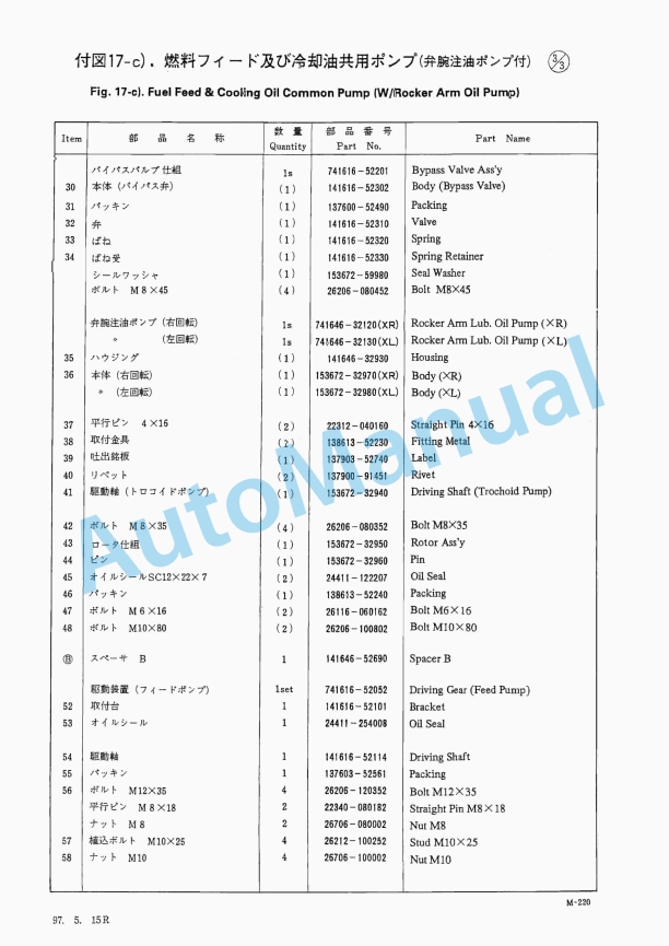
- 15.27. Fig. 17-c). Fuel Feed Pump (with Rocker Arm Lub. Oil pump)
- 15.28. Fig. 17-d). Fuel Feed Cooling Oil Pump (with Rocker Arm Lub. Oil Pump)
- 15.29. Fig. 17-e). Fuel Feed Cooling Oil Pump
- 15.30. Fig. 17-f). Fuel Feed Cooling Oil Common Pump
- 15.31. Fig. 18-a). Fuel Oil No.1 Filter (25A)
- 15.32. Fig. 18-b). Fuel Oil No.1 Filter (40A)
- 15.33. Fig. 18-c). Fuel oil No.1 Filter (50A)
- 15.34. Fig. 19-a). Fuel Oil No.2 Filter (Notch-wire Type)
- 15.35. Fig.19-b). Fuel Oil No.2 Filter (Notch-wire Type)
- 15.36. Fig. 19-c). Fuel Oil No.2 Filter (10μ Heat Insulating)
- 15.37. Fig. 19-d). Fuel oil No.2 Filter (35μ Steam Jacket)
- 15.38. Fig. 19-e). Fuel Oil No.2 Filter (35μ Heat Insulating)
- 15.39. Fig. 20. Lub. Oil Pump
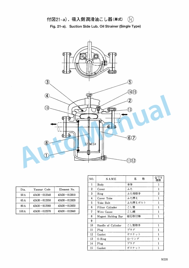
- 15.40. Fig. 21-a). Suction Side Lub. Oil Strainer (Single Type)
- 15.41. Fig. 21-b). Suction Side Lub. Oil Strainer (H Type)
- 15.42. Fig. 22-a). Delivery Side Lub. Oil Strainer (H Type)
- 15.43. Fig. 22-b). Delivery Side Lub. oil Strainer (Notch-wire Type)
- 15.44. Fig. 22-c). Pinion Lub. Oil Stariner (Filter Paper Type)
- 15.45. Fig. 22-d). Indicator for Differentional Pressure
- 15.46. Fig. 23-a). Lub. Oil Cooler (7.28
- 15.47. Fig. 23-b). Lub. Oil Cooler7.28
- 15.48. Fig. 23-c). lub. Oil Cooler (10.3
- 15.49. Fig. 24-a). Lub. Oil Pressure Regulating Valve (for Main Eng.)
- 15.50. Fig. 24-b). Lub. Oil Pressure Regulating Valve (for Auxiliary Eng.)
- 15.51. Fig. 25-a). Lub. Oil Thermostat
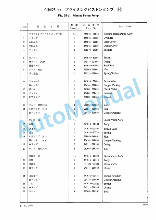
- 15.52. Fig. 25-b). Priming Piston Pump
- 15.53. Fig. 26-a). Cooling Water Pump
- 15.54. Fig. 26-b). Cooling Water Pump
- 15.55. Fig. 27-a). Fuel Oil Pressure Regulating Valve
- 15.56. Fig. 27-b). Cooling Oil Thermostat
- 15.57. Fig. 27-c). Accumulator
- 15.58. Fig. 28. Fuel Injection Valve Leak Pipe
- 15.59. Fig. 29-a). Rocker Arm Oil Feed Pipe System
- 15.60. Fig. 29-b). Pinion Feed Oil Pipe System
- 15.61. Fig. 32-a). Starting Air Distributing Valve
- 15.62. Fig. 32-b). Control Valve
- 15.63. Fig. 32-c). Control Valve (Automatic)
- 15.64. Fig. 33. Starting Valve
- 15.65. Fig. 34. Starting Air Check Valve
- 15.66. Fig. 35. Boost Air Pressure Regurating Device (Optional)
- 15.67. Fig. 36-a). Governor Device
- 15.68. Fig. 36-b). Governor Driving Device
- 15.69. Fig. 37-a). Suction Exhaust Pipe System (for Engine Equipped with Turbocharger on the Flywheel Side)
- 15.70. Fig. 37-b). Suction Exhaust Pipe System (for Engine Equipped with Turbocharger on the Anti-flywheel Side)
- 15.71. Fig. 38-a). Air Cooler (YPC-28 Type)
- 15.72. Fig. 28-b). Air Cooler (YPC-40 Type)
- 15.73. Fig. 39. Starting Air Reservor
- 15.74. Fig. 40. Semi-automatic Blower Washer
- 15.75. Fig. 42. Rocker Arm Lub. Oil Tank
- 15.76. Fig. 40. Steam Trace Pipe System
- 16. YANMARS WORLDWIDE SERVICE NETWORK


,%203GM30(F),%203HM35(F)%20Engine%20Operation%20Manual&url=https://pdfrepairmanual.com/docs/yanmar-1gm10-2gm20f-3gm30f-3hm35f-engine-operation-manual/&media=https://pdfrepairmanual.com/wp-content/uploads/2026/01/yanmar-1gm10-2gm20f-3gm30f-3hm35f-engine-operation-manual-1.jpg)


P,%204LHA-DT(Z)P,%204LHA-ST(Z)P%20Marine%20Diesel%20Engine%20Operation%20Manual&url=https://pdfrepairmanual.com/docs/yanmar-4lha-htzp-4lha-dtzp-4lha-stzp-marine-diesel-engine-operation-manual/&media=https://pdfrepairmanual.com/wp-content/uploads/2026/01/yanmar-4lha-htzp-4lha-dtzp-4lha-stzp-marine-diesel-engine-operation-manual-1.jpg)


There are no reviews yet.