
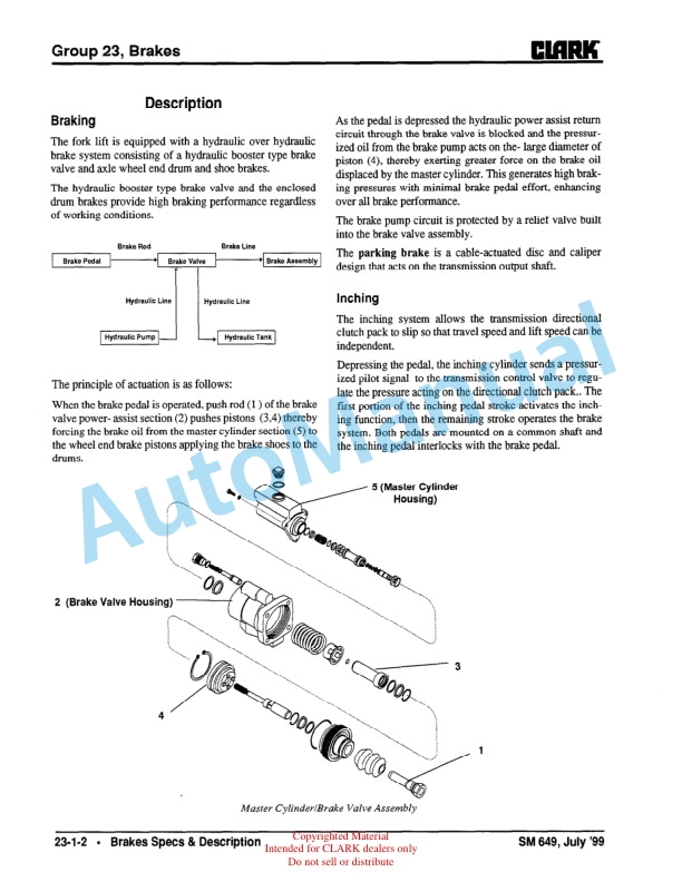
Description
-
Model List:
- CMP 50
- CMP 60
- CMP 70
- 1. SM649 CMP50/60/70
- 2. Use of this Manual
- 3. Contents
- 4. GROUP SA SAFE MAINTENANCE
- 4.1. Section 1. Safety
- 4.2. Section 2. Lifting, Jacking, and Blocking
- 4.2.1. Safe Parking
- 4.2.2. Lifting, Blocking, and Jacking Points
- 4.2.3. Raising Drive Wheels Off Floor
- 4.2.4. Raising Truck with a Hoist
- 4.2.5. Blocking the Upright In Raised Position
- 4.2.6. Raising Rear of Truck
- 4.2.7. Raising Entire Truck
- 4.2.8. Shipping TieDown Instructions
- 4.3. Section 3. Towing
- 5. PERIODIC SERVICE
- 5.1. Section 1. Maintenance Schedules
- 5.1.1. Service Chart/Lubrication Points
- 5.1.2. Recommended Periodic Service Schedule
- 5.2. Section 2. The Planned Maintenance Program
- 5.2.1. Introduction to Planned Maintenance
- 5.2.2. The Basic PM Procedures
- 5.2.3. Visual Inspection
- 5.2.4. Functional Tests
- 5.2.5. Air Cleaning the Truck
- 5.2.6. Truck Chassis Inspection and Lubrication
- 5.2.7. Upright and Tilt Cylinder Lubrication
- 5.2.8. Lift Chain Lubrication
- 5.2.9. UndertheHood Inspection
- 5.2.10. Fluid Checks
- 5.2.11. Stall Test
- 5.2.12. Cranking Voltage Test
- 5.2.13. Critical Fastener Torque Checks
- 5.3. Section 3. The PM Form
- 6. GROUP 00 ENGINE
- 6.1. Lubrication Diagrams
- 6.2. Perkins WORKSHOP MANUAL
- 6.2.1. Contents
- 6.2.2. General information
- 6.2.3. Specifications
- 6.2.4. Cylinder head assembly
- 6.2.5. Piston and connecting rod assemblies
- 6.2.6. Crankshaft assembly
- 6.2.7. Timing case and drive assembly
- 6.2.8. Cylinder block assembly
- 6.2.9. Engines fitted with CAV fuel injection pumps
- 6.2.10. Lubrication system
- 6.2.11. Engines fitted with a rotary fuel injection pump
- 6.2.12. Cooling system
- 6.2.13. Flywheel and flywheel housing
- 6.2.14. Electrical equipment
- 6.2.15. Power steering pump
- 6.2.16. List of special tools
- 7. GROUP 01 COOLING SYSTEM
- 7.1. Section 1. Cooling System Specifications and Description
- 7.2. Section 2. Cooling System Troubleshooting
- 8. GROUP 06 TRANSMISSION
- 8.1. DISASSEMBLY / REASSEMBLY
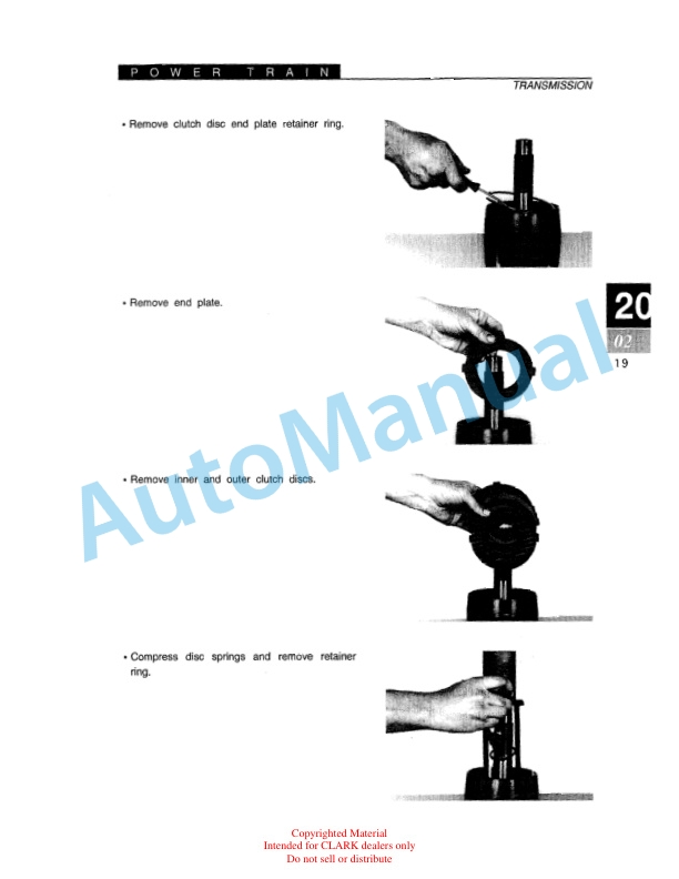
- 8.1.1. DISASSEMBLY AND REASSEMBLY OF(IST) AND 2ND CLUTCH
- 8.1.2. DISASSEMBLY AND REASSEMBLY OF 3RD CLUTCH
- 8.1.3. DISASSEMBLY AND REASSEMBLY OF FORWARD AND REVERSE CLUTCHES
- 8.1.4. REGULATOR VALVE DISASSEMBLY AND REASSEMBLY
- 8.1.5. DISASSEMBLY AND REASSEMBLY OF SPACER PLATE
- 8.1.6. DISASSEMBLY AND REASSEMBLY OF CONVERTER HOUSING
- 8.1.7. OUTPUT FLANGE OIL SEAL SLEEVE DISASSEMBLY AND REASSEMBLY
- 8.1.8. OUTPUT FLANGE AND PARKING BRAKE DISC
- 8.2. REASSEMBLY OF TRANSMISSION
- 8.2.1. ELECTRIC CONTROL VALVE ASSEMBLY
- 8.2.2. DRIVE PLATE INSTALLATION
- 8.2.3. TRANSMISSION TO ENGINE INSTALLATION PROCEDURE
- 8.2.4. SPECIFICATIONS AND SERVICE DATAPOWER SHIFT TRANSMISSION AND TORQUE CONVERTER
- 8.2.5. LUBRICATION
- 8.3. SERVICING MACHINE AFTER TRANSMISSION OVERHAUL
- 8.4. EXTERNAL PLUMBING AND PRESSURE CHECK POINTS
- 8.5. CLEANING AND INSPECTION
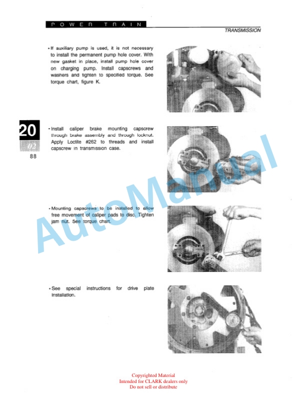
- 8.6. PARKING BRAKE LINING AND PISTON REPLACEMENT PROCEDURE
- 8.7. TROUBLESHOOTING GUIDE FOR THE TRANSMISSION
- 8.7.1. Stall Test
- 8.7.2. Transmission Pressure Checks
- 8.7.3. Mechanical Checks
- 8.7.4. Hydraulic Check
- 8.7.5. CONVERTER STALL PROCEDURE
- 8.7.6. TROUBLESHOOTING GUIDE
- 8.8. SPEED ASSEMBLY INSTRUCTION
- 8.9. ASSEMBLY NOTES
- 8.10. TORQUE SPECIFICATION FOR LUBRICATED OR PLATED SCREWS AND NUTS
- 9. GROUP 14 ELECTRICAL
- 9.1. Section 1. Electrical System Specifications and Circuit Diagram
- 9.2. Section 2. Instrument Pod
- 10. GROUP 20 DRIVE AXLE
- 10.1. Section 1. Drive Axle Specifications and Description
- 10.2. Section 2. Drive Axle Overhaul
- 10.2.1. Overhaul Specifications
- 10.2.2. Drive Axle Disassembly
- 10.2.3. Differential Disassembly
- 10.2.4. Drive Axle Cleaning
- 10.2.5. Drive Axle Inspection
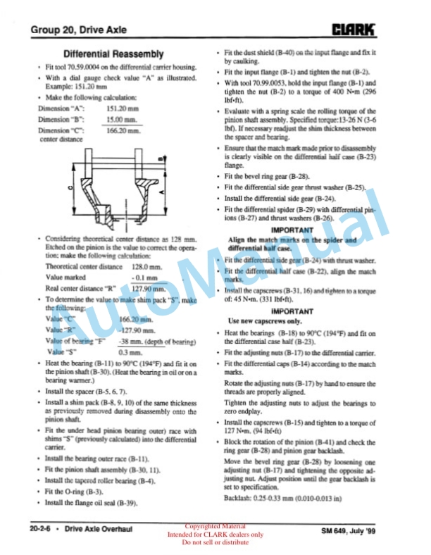
- 10.2.6. Differential Reassembly
- 10.2.7. Drive Axe Reassembly
- 11. GROUP 22 WHEELS AND TIRES
- 11.1. Section 1. Wheels and Tires Specifications and Description
- 11.2. Section 2. Pneumatic Wheels and Tires
- 11.2.1. Pneumatic Tire Maintenance Precaution
- 11.2.2. General Tire Maintenance, Inspection, and Repair
- 11.2.3. Wheel Dismounting and Remounting
- 11.2.4. Drive and Steer Wheel Dismounting
- 11.2.5. Drive and Steer Wheel Remounting
- 11.2.6. DualDrive Wheel Dismounting
- 11.2.7. DualDrive Wheel Remounting
- 11.2.8. Wheel Disassembly and Tire Removal
- 11.2.9. Tire Replacement and Wheel Reassembly
- 11.2.10. TiretoWheel Mounting
- 11.2.11. Filling Tires with Air
- 11.2.12. Filling Tires with Nitrogen
- 11.2.13. Checking and Adjusting Tire Pressure
- 12. GROUP 23 BRAKES
- 12.1. Section 1. Brakes Specifications and Description
- 12.2. Section 2. Service and Inching Brakes
- 12.2.1. Pedals Adjustment
- 12.2.2. Brake Bleeding
- 12.2.3. Removal/Installation of Master Cylinders and Pedal Arramgement
- 12.2.4. Brake Valve Overhaul
- 12.2.5. Brake Shoe and Lining Replacement
- 12.2.6. Wheel Cylinder Inspection
- 12.2.7. Brake Drum Inspection
- 12.2.8. Automatic Adjuster
- 12.2.9. Special Brake Tools
- 12.3. Section 3. Parking Brake
- 12.3.1. Parking Brake Adjustment
- 12.3.2. Lever and Cable Installation
- 12.3.3. Parking Brake Lining and Piston Replacement
- 12.3.4. Parking Brake Adjustment
- 13. GROUP 25/26 STEERING SYSTEM
- 13.1. Section 1. Steering System Specifications and Description
- 13.1.1. Specifications
- 13.1.2. Description
- 13.1.3. Schematic
- 13.1.4. Construction
- 13.1.5. Operation
- 13.2. Section 2. Steering System Troubleshooting
- 13.3. Section 3. Steering System Removals and Replacements
- 13.4. Section 4. Steering System Pressure Check and Adjustment
- 13.5. Section 5. Steering Unit Overhaul
- 13.6. Section 6. Priority Valve Overhaul
- 13.7. Section 7. Steer Cylinder Overhaul
- 14. GROUP 29/30 HYDRAULIC SYSTEM
- 14.1. Section 1. Hydraulic System Specifications Schematic Diagram
- 14.2. Section 2. Hydraulic System Troubleshooting
- 14.2.1. Pressure Check and Adjustment
- 14.2.2. Control Valve Troubleshooting
- 14.3. Section 3. Hydraulic Pump Overhaul
- 14.3.1. Main and Auxiliary Pumps Removal and Replacement
- 14.3.2. Main and Auxiliary Pump Overhaul
- 14.4. Section 4. Hydraulic Valve Overhaul
- 14.4.1. Removal and Replacement
- 14.4.2. Description
- 14.4.3. Disassembly
- 14.4.4. Assembly
- 14.4.5. Inspection and Assessment
- 15. GROUP 34 UPRIGHT
- 15.1. Section 1. Upright Specifications and Description
- 15.2. Section 2. Upright Checks and Adjustments
- 15.2.1. Performing Visual Inspection
- 15.2.2. Checking and Adjusting Carriage Side Roller
- 15.2.3. Checking Carriage and Mast Shim
- 15.2.4. Adjusting Standard Mast Shim
- 15.2.5. Adjusting Full Free Lift TwoStage Mast Shim
- 15.2.6. Adjusting Full Free Lift ThreeStage Mast Shim
- 15.2.7. Checking and Adjusting Cylinder Racking
- 15.3. Section 3. Lift Chain Service
- 15.4. Section 4. Removals and Replacements
- 15.4.1. Removing and Installing Mast
- 15.4.2. Carriage Removal and Replacement
- 15.5. Section 5. Lift and Tilt Cylinder Overhaul
- 16. GROUP 38 COUNTERWEIGHT
- 16.1. Section 1. Specifications
- 16.2. Section 2. Inspection
- 16.3. Section 3. Removal and Replacement
- 17. GROUP 40 SPECIFICATIONS
- 17.1. Section 1. Specifications
- 17.1.1. Dimensions and Weight Specifications
- 17.1.2. Performance Specifications
- 17.1.3. Service Specifications by Group
- 17.1.4. Fluids Specifications
- 17.1.5. Critical Torque Specifications
- 17.1.6. Standard Tightening Torque
- 17.1.7. Metric Conversion Chart
- 17.1.8. Hydraulic Fitting Tightening Procedure


There are no reviews yet.