
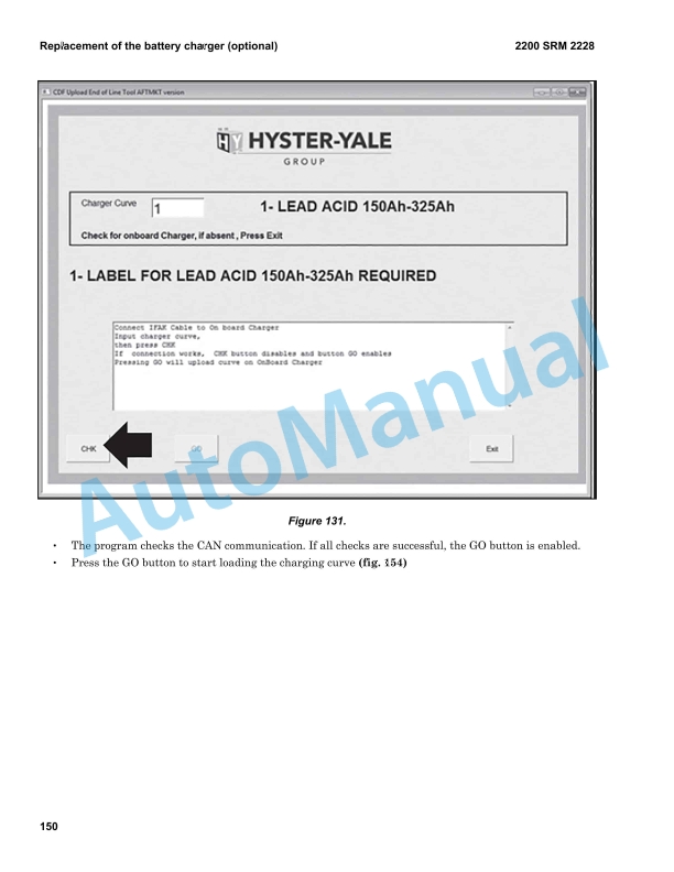
Description
-
Model List:
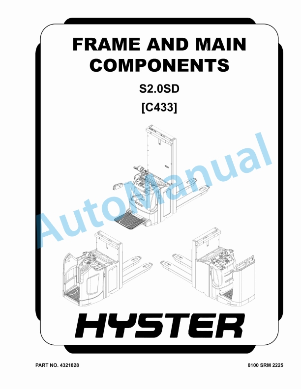
- S2.0SD (C433) Frame And Main Components
- 1. RM2225-(08-2022)-UK-EN
- 1.1. Important
- 1.2. General safety rules
- 1.3. Torque settings for screws nuts and fittings
- 1.4. Correct method for applying female fittings
- 1.5. Instruction for installing flexible hoses and fittings
- 1.6. Truck presentation
- 1.7. Views of the truck
- 1.8. Truck and load identification data
- 1.9. General specification
- 1.10. Traction wheel
- 1.11. Removal of the traction wheel
- 1.12. Torsion bar caster wheel group disassembly
- 1.13. Torsion bar caster wheel assembly
- 1.14. Replacing the caster wheel
- 1.15. Replacing the caster wheel group
- 1.16. Load wheels
- 1.17. Replacing the single load wheel
- 1.18. Replacing the optional tandem load wheel
- 1.19. Replacing the single load wheel assembly
- 1.20. Replacing the optional tandem load wheel assembly
- 1.21. Fixed linkage
- 1.22. Removal of the linkage assembly
- 1.23. Key to tiller components
- 1.24. Tiller spring replacement
- 1.25. Adjustable steering spring replacement
- 1.26. Tiller removal
- 1.27. Replacement of the potentiometer and tiller base bearings of the fixed tiller
- 1.28. Replacement of the potentiometer and tiller base bearings of the optional adjustable steering
- 1.29. Key to scooter control components
- 1.30. Scooter control head removal
- 1.31. Scooter control spring replacement
- 1.32. Replacement of the scooter control sensor and base bearings
- 1.33. Side gate replacement
- 1.34. Side gates microswitch replacement
- 1.35. Removal of the platform gas spring
- 1.36. Replacement of the platform touchless sensor
- 1.37. Removal of the platform
- 1.38. Replacement of the platform sensor
- 1.39. Traction motor
- 1.40. Motor dismantling
- 1.41. Steering motor
- 1.42. Steering motor dismantling
- 2. RM2226-(08-2022)-UK-EN
- 2.1. Before Installation
- 2.2. Truck assembly
- 2.3. Topping up the oil reservoir
- 2.4. Installation of the battery with lateral extraction
- 2.5. Connection of cables to battery
- 2.6. List and description of the settings and adjustments to be carried out
- 3. RM2227-(08-2022)-UK-EN
- 3.1. Description of controller connectors
- 3.2. Device properties
- 3.3. Monitor menu
- 3.4. Troubleshooting
- 3.5. Warnings
- 3.6. Diagnosis system for F2-C Controller
- 3.7. Diagnosis system for Integrated Steering System
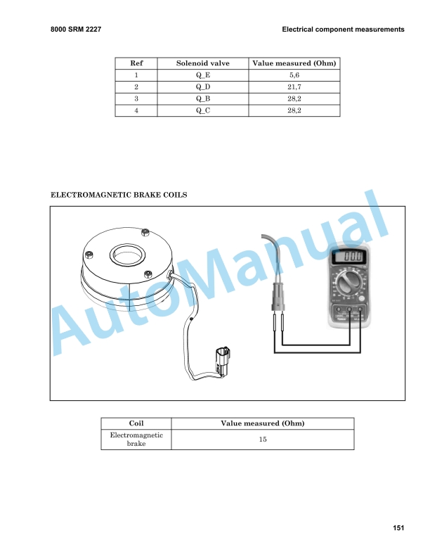
- 3.8. Electrical component measurements
- 4. RM2228-(11-2022)-UK-EN
- 4.1. Wiring diagrams
- 4.2. Electrical components
- 4.3. Identification of the tiller head controls and of the operator panel instruments
- 4.4. Display
- 4.5. Optional keypad
- 4.6. Instructions for the use of the new keypad application
- 4.7. Truck functions
- 4.8. Controller F2-C
- 4.9. Controller F1 – Si
- 4.10. Installation procedure of Curtis Integrated Toolkit
- 4.11. Instructions for the use of Curtis Integrated Toolkit Software
- 4.12. Instructions to update Curtis Integrated Toolkit Software
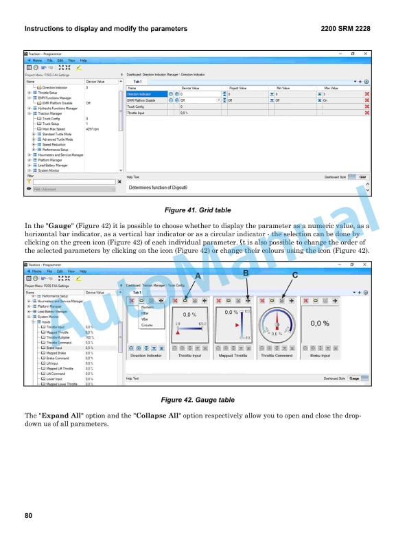
- 4.13. Instructions to display and modify the parameters
- 4.14. Description of standard F2-C parameters
- 4.15. Description of standard ISS parameters
- 4.16. CDF file installation procedure
- 4.17. Replacement of the controllers
- 4.18. Replacement of the display
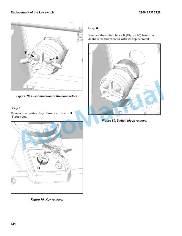
- 4.19. Replacement of the key switch
- 4.20. Replacement of the keypad (optional)
- 4.21. Replacement of the general emergency switch
- 4.22. Replacement of the horn
- 4.23. Replacement of the fuses
- 4.24. Replacement of the main contactor switch
- 4.25. Replacement of the fork lift cutout sensor
- 4.26. Replacement of the tiller sensor
- 4.27. Replacement of the tiller board
- 4.28. Replacement of tiller control springs
- 4.29. Replacement of tiller buttons
- 4.30. Replacement of the centred wheel sensor
- 4.31. Replacement of the Low Side Driver (LSD)
- 4.32. Replacement of the battery charger (optional)
- 4.33. Replacement of the back-up alarm (optional)
- 4.34. Replacement of the DC/DC converter (optional)
- 4.35. Replacement of the working light (optional)
- 4.36. Replacement of the Pedestrian Awareness Light (optional)
- 5. RM2229-(08-2022)-UK-EN
- 5.1. Hydraulic functions
- 5.2. Hydraulic diagrams
- 5.3. Hydraulic diagrams for various functions
- 5.4. Hydraulic components
- 5.5. Dismantling of cartridge soilenoid valves
- 5.6. Cylinders
- 5.7. Removal of the initial lift cylinder
- 5.8. Removal of the cylinder head bushing
- 5.9. Dismantling of central lift cylinder
- 5.10. Replacement of upper gaskets on the central lift cylinder
- 5.11. Replacement of lower gaskets on the central lift cylinder
- 5.12. Hydraulic power unit removal
- 5.13. Hydraulic power unit disassembly
- 6. RM2230-(08-2022)-UK-EN
- 6.1. Mast characteristics
- 6.2. Mast assembly components
- 6.3. Dismantling the complete column
- 6.4. Dismantling the inner mast stage
- 6.5. Replacement of chains and chain tensioner
- 6.6. Fork small mast
- 6.7. Removal of the fork small mast
- 7. RM2231-(08-2022)-UK-EN
- 7.1. Identification of the master drive unit
- 7.2. Removal and disassembly of the reduction unit
- 7.3. Removal and replacement of the master drive unit springs
- 7.4. Removal and replacement of the master drive unit dampening lever
- 7.5. Braking System
- 7.6. Removal of the electromagnetic brake
- 8. RM2232-(08-2022)-UK-EN
- 8.1. Maintenance Warnings
- 8.2. Oils and Lubricants
- 8.3. Cleaning products
- 8.4. Scheduled Maintenance
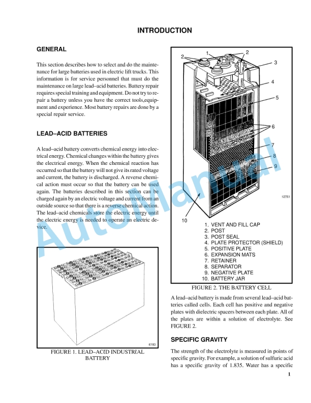
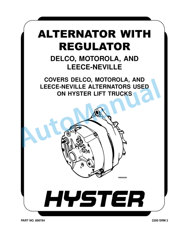
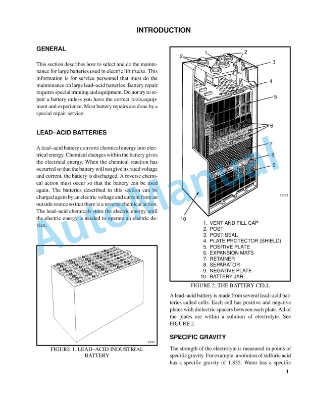
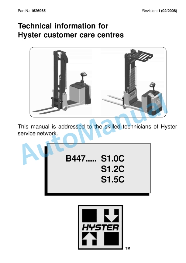
%20Frame%20And%20Main%20Components%20Service%20Manual&url=https://pdfrepairmanual.com/docs/hyster-s2-0sd-c433-frame-and-main-components-service-manual/&media=https://pdfrepairmanual.com/wp-content/uploads/2026/01/hyster-s20sd-c433-frame-and-main-components-service-manual-1.jpg)
%20Service%20Manual&url=https://pdfrepairmanual.com/docs/hyster-b210-n30ah-service-manual/&media=https://pdfrepairmanual.com/wp-content/uploads/2026/01/hyster-b210-n30ah-service-manual-1.jpg)

%20Service%20Manual&url=https://pdfrepairmanual.com/docs/hyster-b160-j25-35bs-service-manual/&media=https://pdfrepairmanual.com/wp-content/uploads/2026/01/hyster-b160-j25-35bs-service-manual-1.jpg)
%20Service%20Manual&url=https://pdfrepairmanual.com/docs/hyster-a406-r1-4-r1-6-service-manual/&media=https://pdfrepairmanual.com/wp-content/uploads/2026/01/hyster-a406-r14-r16-service-manual-1.jpg)
%20Maintenance%20Schedule&url=https://pdfrepairmanual.com/docs/hyster-c098-e3-50-5-50xl-e4-50xls-maintenance-schedule/&media=https://pdfrepairmanual.com/wp-content/uploads/2026/01/hyster-c098-e350-550xl-e450xls-maintenance-schedule-1.jpg)
%20Service%20Manual&url=https://pdfrepairmanual.com/docs/hyster-b174-r30es-service-manual/&media=https://pdfrepairmanual.com/wp-content/uploads/2026/01/hyster-b174-r30es-service-manual-1.jpg)

%20Service%20Manual&url=https://pdfrepairmanual.com/docs/hyster-b447-s1-0c-s1-2c-s1-5c-service-manual/&media=https://pdfrepairmanual.com/wp-content/uploads/2026/01/hyster-b447-s10c-s12c-s15c-service-manual-1.jpg)
%20Service%20Manual&url=https://pdfrepairmanual.com/docs/hyster-b460-k1-0m-k1-0h-k1-0h-wp-service-manual/&media=https://pdfrepairmanual.com/wp-content/uploads/2026/01/hyster-b460-k10m-k10h-k10h-wp-service-manual-1.jpg)
%20Service%20Manual&url=https://pdfrepairmanual.com/docs/hyster-c001-h1-25-1-75xl-service-manual/&media=https://pdfrepairmanual.com/wp-content/uploads/2026/01/hyster-c001-h125-175xl-service-manual-1.jpg)
There are no reviews yet.