
Description
-
Model List:
- D375A-8E0 Bull Dozer
- 1. Cover
- 2. Preface
- 3. CONTENTS
- 4. Specifications
- 5. Precautions for field assembly
- 6. Disposal of removed parts
- 7. Assembly procedure, necessary equipment, and schedule
- 8. Layout of kit
- 9. Style for transportation
- 10. Table of tools for field assembly
- 11. Tightening torque
- 12. Coating materials list
- 13. Selection of wire ropes used for assembly
- 14. Assembly
- 14.1. A1 Installation of chassis
- 14.2. A2 Installation of final drive assy
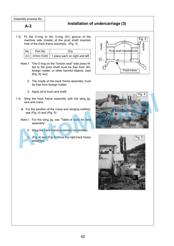
- 14.3. A3 Installation of undercarriage
- 14.4. A4 Adding oil to recoil chamber and pivot chamber
- 14.5. A5 Installing direction of exhaust pipe
- 14.6. A6 Installation of blade lift cylinder
- 14.7. A7 Installation of cylinder yoke grease hose
- 14.8. A8 Installation of ripper
- 14.9. A9 Installation of grease hose of ripper pin
- 14.10. A10 Installation of track
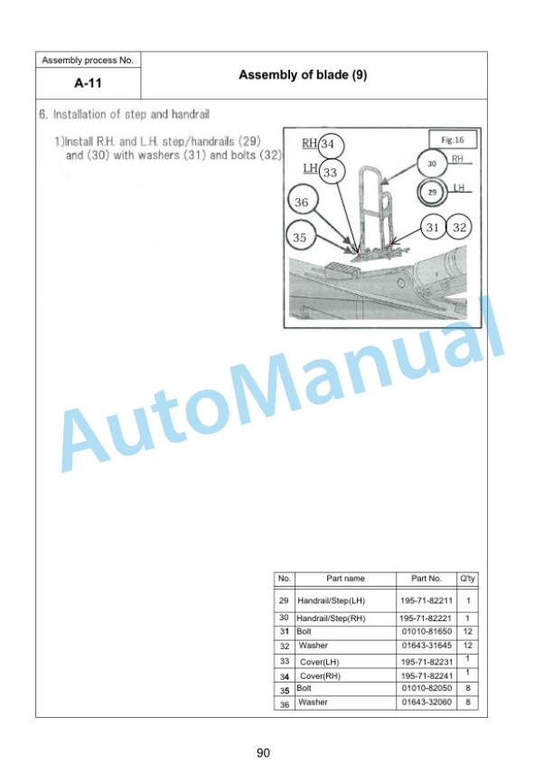
- 14.11. A11 Assembly of blade
- 14.12. A12 Installation of blade
- 14.13. A13 Installation of KOMTRAX antenna
- 14.14. A14 Installation of ROPS guard
- 14.15. A15 Installation of platform
- 14.16. A16 Installation of AUX BOX
- 14.17. A17 Check track tension
- 14.18. A18 Check fuel, coolant and lubricants
- 14.19. A19 Bleeding air from hydraulic cylinders
- 14.20. A20 Lubricating
- 14.21. A21 Installation of fuel quick charge piping
- 14.22. A22 Installation of ladder
- 15. Check and maintenance procedures after completion of assembly
- 15.1. M1 Inspection of machine monitor
- 15.2. M2 Setting procedure for USER ADJUST MODE
- 15.3. M3 Replacement of return filter
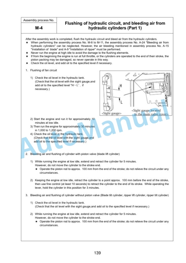
- 15.4. M4 Flushing of hydraulic circuit, and bleeding air from hydraulic cylinders
- 15.5. M5 Replacement of return filter
- 15.6. M6 Bleeding air from hydraulic cylinders
- 15.7. M7 Method for starting up KOMTRAX terminal and default setting of KOMTRAX Plus controller etc
- 16. CALIBRATION OF CUTTING EDGE
- 16.1. Operations and checks after starting engine
- 16.2. Procedure 1. Adjustment ID 8041 (iB MACHINE SPEC SET MODE)
- 16.3. Procedure 2. Resetting of cylinder stroke end
- 16.4. Procedure 3. Adjustment ID 8043 (Adjustment of installed lengths of R.H. and L.H. lift cylinders)
- 16.5. Procedure 4. Adjustment ID 8044 (L.H. tilt cylinder automatic adjustment)
- 16.6. Procedure 5. Adjustment ID 8048 (AUTO PITCH ADJUST)
- 16.7. Procedure 6. Adjustment ID 8040 (CYLINDER CALIBRATION MODE)
- 16.8. Procedure 7. Adjustment ID 8042 (iB W/E VALVE AUTO SET MODE)
- 16.9. Procedure 8. Inputting wear amount of blade edge and track shoe
- 16.10. Procedure 9. 10. Special functions of control box
- 16.11. Procedure 9. Operation of Machine Cal Step A menu
- 16.12. Procedure 10. Operation of Machine Cal Step B menu
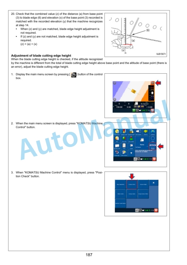
- 16.13. Procedure 11. Checking and adjusting blade edge elevation
- 17. Field assembly inspection report



There are no reviews yet.