

Description
-
Model List:
- S1.0C, S1.2C, S1.5C (C447)
- 1. RM2233-(01-2023)-UK-EN
- 1.1. Important
- 1.2. General safety rules
- 1.3. Torque settings for screws nuts and fittings
- 1.4. Correct method for applying female fittings
- 1.5. Instruction for installing flexible hoses and fittings
- 1.6. Truck presentation
- 1.7. Views of the truck
- 1.8. Truck and load identification data
- 1.9. General specification
- 1.10. Traction wheel
- 1.11. Removal of the traction wheel
- 1.12. Load wheels
- 1.13. Replacing the single load wheel
- 1.14. Key to tiller components
- 1.15. Removal/Replacement of the upper panel
- 1.16. Tiller assembly removal
- 1.17. Replacement of the tiller base bearings
- 1.18. Tiller spring replacement
- 1.19. Tiller replacement
- 1.20. Traction motor
- 1.21. Traction motor dismantling
- 1.22. Steering motor
- 1.23. Steering motor dismantling
- 2. RM2234-(01-2023)-UK-EN
- 2.1. Before Installation
- 2.2. Machine assembly
- 2.3. Topping up the oil reservoir
- 2.4. Installation of the battery with vertical extraction
- 2.5. Connection of cables to battery
- 2.6. List and description of the settings and adjustments to be carried out
- 2.7. Battery voltage setting
- 3. RM2235-(01-2023)-UK-EN
- 3.1. Description of module connectors
- 3.2. Tester menu
- 3.3. Troubleshooting
- 3.4. Diagnosis system for Combi Module
- 3.5. Diagnosis system for EPS AC0
- 3.6. Electrical component measurements
- 4. RM2236-(01-2023)-UK-EN
- 4.1. Wiring diagrams
- 4.2. Electrical components
- 4.3. Identification of the tiller head controls and of the operator panel instruments
- 4.4. Display
- 4.5. Optional keypad
- 4.6. Instructions for the use of the new keypad application
- 4.7. Truck functions
- 4.8. Electric steering
- 4.9. Procedure for access to configuration parameters
- 4.10. Combi Module
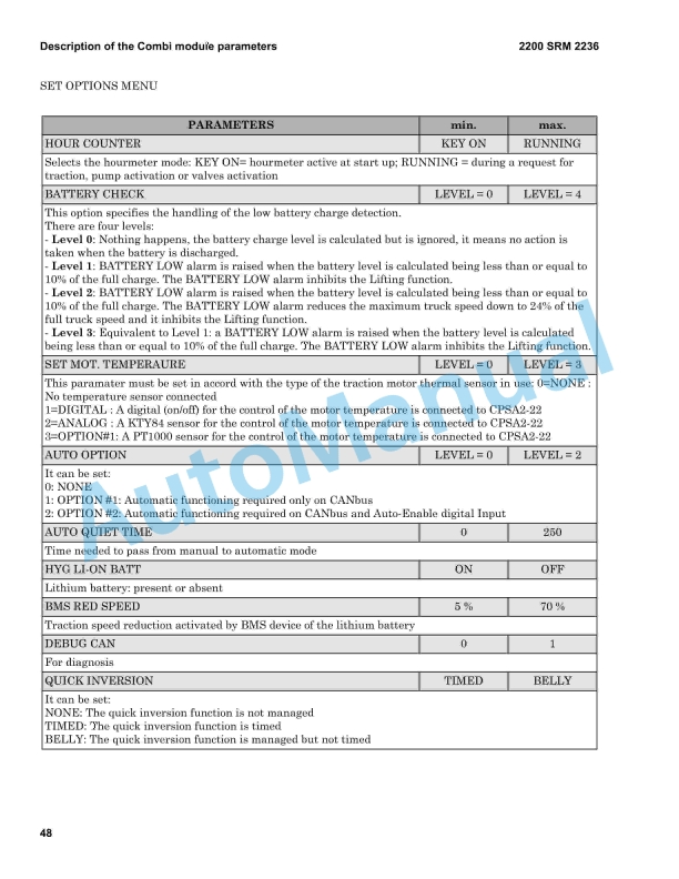
- 4.11. Description of the Combi module parameters
- 4.12. EPS – AC0 module
- 4.13. Description of the EPS-AC0 module parameters
- 4.14. Replacement of the controller Combi
- 4.15. Replacement of the controller EPS-AC0 – Steering calibration
- 4.16. Replacement of the display
- 4.17. Replacement of the key switch
- 4.18. Replacement of the keypad (optional)
- 4.19. Replacement of the general emergency switch
- 4.20. Replacement of the horn
- 4.21. Replacement of the auxiliary relays
- 4.22. Replacement of the fuses
- 4.23. Replacement of the main contactor switch
- 4.24. Replacement of the fork lifting sensor 500 mm
- 4.25. Replacement of the steering tiller cabled sensor
- 4.26. Replacement of the tiller sensor
- 4.27. Replacement of the tiller board
- 4.28. Replacement of tiller control springs
- 4.29. Replacement of tiller buttons
- 4.30. Replacement of the centred wheel sensor
- 4.31. Replacement of the Pedestrian Awareness Light (optional)
- 5. RM2237-(01-2023)-UK-EN
- 5.1. Hydraulic functions
- 5.2. Hydraulic diagrams
- 5.3. Hydraulic diagrams for various functions
- 5.4. Hydraulic components
- 5.5. Replacement of maximum pressure valve
- 5.6. Proportional solenoid valve for the fork lowering (EV1)
- 5.7. On/off solenoid valve for the fork lifting (EV2)
- 5.8. Solenoid valves EV3 – EV4 – EV5 – EV6
- 5.9. Replacement of the valve SB
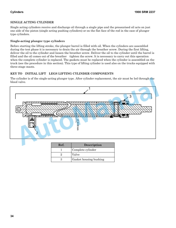
- 5.10. Cylinders
- 5.11. Fork tilting cylinder
- 5.12. Fork positioner cylinder
- 5.13. Removal of the central free lift cylinder
- 5.14. Replacement of the central free lift cylinder gasket
- 5.15. Removal of main lift cylinder
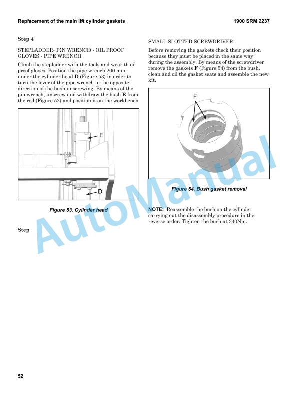
- 5.16. Replacement of the main lift cylinder gaskets
- 5.17. Replacement of the feeding pipe central free lift cylinder
- 5.18. Replacement of the twin-pipes feeding the tilting cylinders and the fork positioner
- 6. RM2238-(01-2023)-UK-EN
- 6.1. Mast characteristics
- 6.2. Mast assembly components
- 6.3. Dismantling the complete column
- 6.4. Dismantling the inner mast stage
- 6.5. Dismantling the intermediate mast
- 6.6. Replacement of the main lift chains
- 6.7. Replacement of the side cylinders chain sheaves
- 6.8. Replacement of free lift chain – 3 STG FFL
- 6.9. Disassembly of the hydraulic pipe pulley – central cylinder
- 6.10. Disassembly and replacement of the central chain pulley
- 6.11. Fem Fork Carriage
- 6.12. Sideshift carriage
- 6.13. Removal of the sideshift carriage
- 7. RM2239-(01-2023)-UK-EN
- 7.1. Identification of the master drive unit
- 7.2. Removal and disassembly of the reduction unit
- 7.3. Braking System
- 7.4. Electromagnetic brake components
- 7.5. Removal of the electromagnetic brake
- 7.6. Adjustment of the electromagnetic brake
- 8. RM2240-(01-2023)-UK-EN
- 8.1. Maintenance Warnings
- 8.2. Oils and Lubricants
- 8.3. Cleaning products
- 8.4. Scheduled Maintenance
%20Frame%20And%20Main%20Components%20Maintenance%20And%20Repair&url=https://pdfrepairmanual.com/docs/hyster-s1-0c-s1-2c-s1-5c-c447-frame-and-main-components-maintenance-and-repair/&media=https://pdfrepairmanual.com/wp-content/uploads/2026/01/hyster-s10c-s12c-s15c-c447-frame-and-main-components-maintenance-and-repair-1.jpg)


%20Service%20Manual&url=https://pdfrepairmanual.com/docs/hyster-c007-h150-275hp150-200b-service-manual/&media=https://pdfrepairmanual.com/wp-content/uploads/2026/01/hyster-c007-h150-275hp150-200b-service-manual-1.jpg)

%20Service%20Manual&url=https://pdfrepairmanual.com/docs/hyster-b210-n30ah-service-manual/&media=https://pdfrepairmanual.com/wp-content/uploads/2026/01/hyster-b210-n30ah-service-manual-1.jpg)


%20Service%20Manual&url=https://pdfrepairmanual.com/docs/hyster-c010-s1-50-2-00xms-service-manual/&media=https://pdfrepairmanual.com/wp-content/uploads/2026/01/hyster-c010-s150-200xms-service-manual-1.jpg)
%20Service%20Manual&url=https://pdfrepairmanual.com/docs/hyster-c005-h60-90c-service-manual/&media=https://pdfrepairmanual.com/wp-content/uploads/2026/01/hyster-c005-h60-90c-service-manual-1.jpg)
%20Service%20Manual&url=https://pdfrepairmanual.com/docs/hyster-b168-j40-60xl-service-manual/&media=https://pdfrepairmanual.com/wp-content/uploads/2026/01/hyster-b168-j40-60xl-service-manual-1.jpg)
There are no reviews yet.