JCB G130RX to G220QX Operator Manual 9811-4650
$20.00
- Type Of Manual: Operator Manual
- ManualID: 9811-4650
- Number of Pages: 132
- Size: 14.4MB
- Format: PDF
Description
-
Model List:
- G130RX, G144X, G144QX, G160RX, G175X, G175QX, G200RX, G220X, G220QX
- 1. Introduction
- 2. Machine Model and Serial Number ………………………………………………………1
- 3. About This Manual ……………………………………………………………………………..2
- 4. Cross References ………………………………………………………………………….2
- 5. Component Identification …………………………………………………………………….3
- 6. Data plate …………………………………………………………………………………….4
- 7. Important Information …………………………………………………………………………5
- 8. The Operator Manual …………………………………………………………………….5
- 9. Safety Warnings ……………………………………………………………………………5
- 10. Safety, Yours and Others …………………………………………………………………….6
- 11. Checklists …………………………………………………………………………………………7
- 12. General Safety ……………………………………………………………………………..7
- 13. Operating Safety …………………………………………………………………………..8
- 14. Maintenance Safety ……………………………………………………………………….9
- 15. Installation
- 16. Unpacking ……………………………………………………………………………………….13
- 17. Site Installation ………………………………………………………………………………..14
- 18. Outdoor Installations. ………………………………………………………………………..15
- 19. Indoor installations ……………………………………………………………………………16
- 20. Generator Set Room ……………………………………………………………………16
- 21. Basic Elements to be considered …………………………………………………..21
- 22. Routine Maintenance
- 23. Service Requirements ………………………………………………………………………22
- 24. Health and Safety …………………………………………………………………………….23
- 25. Lubricants …………………………………………………………………………………..23
- 26. Service Schedules ……………………………………………………………………………25
- 27. Introduction …………………………………………………………………………………25
- 28. How to Use the Service Schedules ………………………………………………..25
- 29. Service Schedule Checklist …………………………………………………………..26
- 30. Battery ……………………………………………………………………………………………28
- 31. Connection and Disconnection (battery arrangement) ………………………28
- 32. Charging the Battery ……………………………………………………………………28
- 33. Battery Maintenance ……………………………………………………………………28
- 34. Battery Life …………………………………………………………………………………28
- 35. Cooling System ……………………………………………………………………………….29
- 36. Checking and Adding Coolant ……………………………………………………….29
- 37. Coolant Mixtures …………………………………………………………………………29
- 38. Cleaning the Radiator …………………………………………………………………..30
- 39. Pre Start Checks ………………………………………………………………………………31
- 40. Checks After Running ……………………………………………………………………….32
- 41. Cleaning …………………………………………………………………………………………33
- 42. CP1 and CP2 Digital Control Panels
- 43. Introduction ……………………………………………………………………………………..34
- 44. The panel provides the following readings of the electric mains supply: 34
- 45. The panel provides the following engine features information: …………..34
- 46. The panel controls the following functions of the engine: …………………..34
- 47. Password ……………………………………………………………………………………35
- 48. Control Panel Front Views …………………………………………………………………36
- 49. CP1 …………………………………………………………………………………………..36
- 50. CP2 …………………………………………………………………………………………..37
- 51. Control Panel Push Buttons ………………………………………………………………38
- 52. Operating mode buttons ……………………………………………………………….38
- 53. Command buttons ……………………………………………………………………….38
- 54. Display Buttons …………………………………………………………………………..39
- 55. Contactors Buttons (CP2 only) ………………………………………………………39
- 56. Data LEDs ………………………………………………………………………………………40
- 57. Engine Status LEDs …………………………………………………………………….40
- 58. Alarm LEDs ………………………………………………………………………………..40
- 59. Electric Power Status LEDs …………………………………………………………..41
- 60. Starting and Stopping – Manual Mode …………………………………………………42
- 61. Starting ………………………………………………………………………………………42
- 62. Stopping …………………………………………………………………………………….42
- 63. Starting and Stopping – Automatic Mode ……………………………………………..43
- 64. Operational Modes …………………………………………………………………………..44
- 65. Test Mode (CP2 only) …………………………………………………………………..44
- 66. Block Mode (CP1 only) …………………………………………………………………44
- 67. Block Mode (CP2 only) …………………………………………………………………44
- 68. Activation of Contactors (CP2 only) ……………………………………………….45
- 69. Linking Generators and Transfer Panels …………………………………………45
- 70. Alarms ……………………………………………………………………………………………46
- 71. Engine Alarms …………………………………………………………………………….46
- 72. Generator Set Alarms …………………………………………………………………..47
- 73. Mains Alarms (CP2 only) ………………………………………………………………47
- 74. Transfer Fuel Pump (Optional) …………………………………………………………..48
- 75. ATP1 Digital Control Panel (option)
- 76. Introduction ……………………………………………………………………………………..49
- 77. The automatic transfer panel provides the following readings of the electric
- 78. mains supply: ……………………………………………………………………………..49
- 79. Outputs to allow Monitoring of Controller Operating Conditions …………49
- 80. Control Panel Front View …………………………………………………………………..50
- 81. Control Panel Push Buttons ………………………………………………………………51
- 82. Operating mode buttons ……………………………………………………………….51
- 83. Command buttons ……………………………………………………………………….52
- 84. Display Buttons …………………………………………………………………………..52
- 85. Contactors Buttons ………………………………………………………………………52
- 86. Data LEDs ………………………………………………………………………………………53
- 87. Starting and Stopping – Manual Mode …………………………………………………54
- 88. Starting ………………………………………………………………………………………54
- 89. Stopping …………………………………………………………………………………….54
- 90. Starting and Stopping – Automatic Mode ……………………………………………..55
- 91. Introduction …………………………………………………………………………………55
- 92. Starting ………………………………………………………………………………………55
- 93. Stopping …………………………………………………………………………………….55
- 94. Operational Modes …………………………………………………………………………..56
- 95. Integrated Generator Set Mode ……………………………………………………..56
- 96. Test Mode …………………………………………………………………………………..56
- 97. Block Mode …………………………………………………………………………………56
- 98. Activation of Contactors ……………………………………………………………….56
- 99. Inputs and Outputs …………………………………………………………………………..57
- 100. Digital Input (Non Programmable) ………………………………………………….57
- 101. Programmable Inputs …………………………………………………………………..57
- 102. Digital Outputs …………………………………………………………………………….57
- 103. Alarms ……………………………………………………………………………………………58
- 104. Electrical Characteristics …………………………………………………………………..62
- 105. Wiring Diagrams ………………………………………………………………………….63
- 106. Alternator
- 107. Introduction ……………………………………………………………………………………..64
- 108. Safety Precautions ………………………………………………………………………64
- 109. Designation ………………………………………………………………………………..64
- 110. Installation ………………………………………………………………………………………65
- 111. Lifting …………………………………………………………………………………………65
- 112. AVR Settings and Type ………………………………………………………………..66
- 113. Protection …………………………………………………………………………………..69
- 114. Alternator Terminal Connections ………………………………………………………..70
- 115. Series Star ………………………………………………………………………………….70
- 116. Parallel Star ………………………………………………………………………………..70
- 117. Series Delta ………………………………………………………………………………..71
- 118. Double Delta ……………………………………………………………………………….71
- 119. Parallel Zig-Zag …………………………………………………………………………..72
- 120. Fault Finding ……………………………………………………………………………………73
- 121. Service and Maintenance ………………………………………………………………….76
- 122. Winding Condition ……………………………………………………………………….76
- 123. Winding Condition Assessment ……………………………………………………..76
- 124. Spares and After Sales Service ………………………………………………………….77
- 125. Ordering Parts …………………………………………………………………………….77
- 126. Engine Maintenance
- 127. Introduction ……………………………………………………………………………………..78
- 128. Component Identification (N67 TE2A) …………………………………………….78
- 129. Component Identification (NEF 67 TM) …………………………………………..79
- 130. Warning Signs …………………………………………………………………………….80
- 131. Electrical Precautions …………………………………………………………………..80
- 132. Engine Electrics ……………………………………………………………………………….81
- 133. Electrical Interconnection Unit – N 67 only ………………………………………81
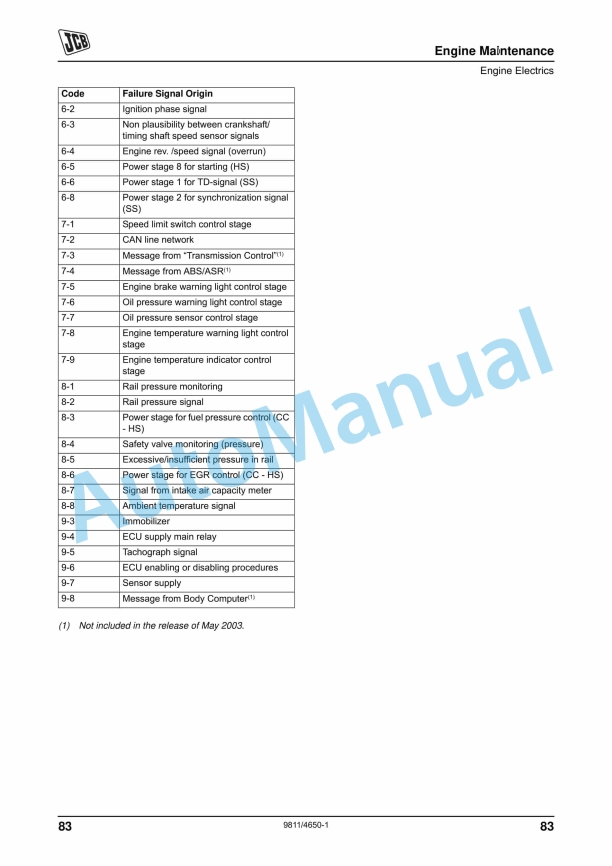
- 134. Failure Code Decoding – N 67 Only ……………………………………………….82
- 135. Engine Oil and Filter …………………………………………………………………………84
- 136. Recommended Oils ……………………………………………………………………..84
- 137. Engine Oil Capacity ……………………………………………………………………..84
- 138. Checking the Oil Level …………………………………………………………………85
- 139. Changing the Oil and Filter ……………………………………………………………86
- 140. Changing the Oil Vapour Filter (N 67 TE2 Engine) …………………………..87
- 141. Cooling System ……………………………………………………………………………….88
- 142. Checking and Adjusting Drive Belt with Automatic Tensioning (NE 67 TE2
- 143. Engine) ………………………………………………………………………………………88
- 144. Checking and Adjusting Drive Belt (NEF 67 Engine) ………………………..89
- 145. Drain and Refill the Coolant ………………………………………………………….90
- 146. Fuel System …………………………………………………………………………………….91
- 147. Diesel Fuel …………………………………………………………………………………91
- 148. Priming the Fuel System ………………………………………………………………91
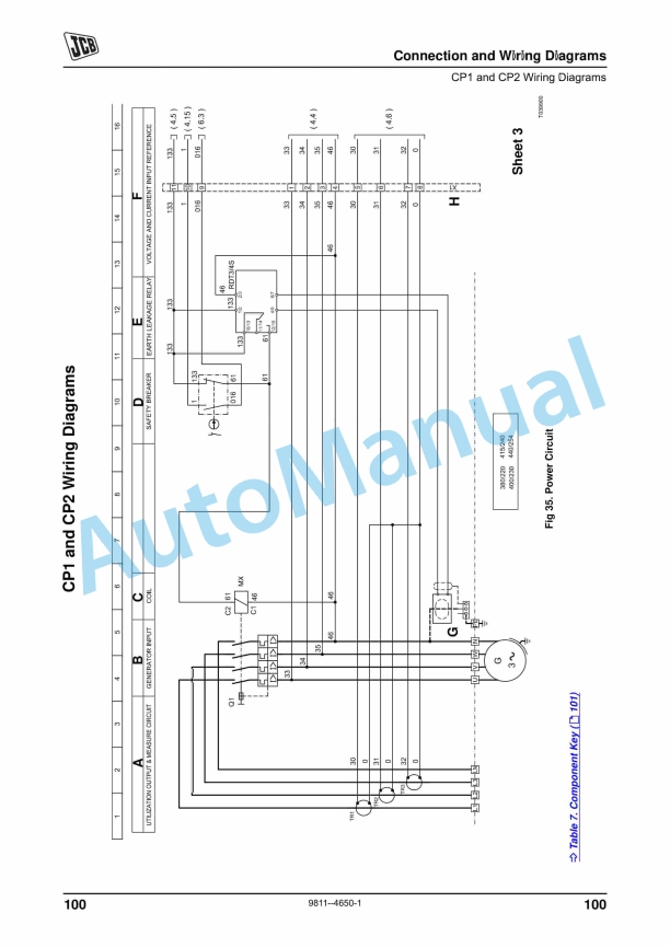
- 149. To Drain the Filters or Pre-filter ……………………………………………………..93
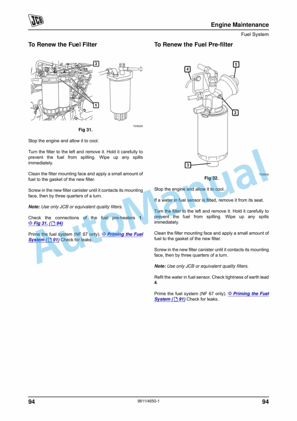
- 150. To Renew the Fuel Filter ………………………………………………………………94
- 151. To Renew the Fuel Pre-filter ………………………………………………………….94
- 152. Inlet and Exhaust System ………………………………………………………………….95
- 153. To Renew the Air Cleaner Outer Element ……………………………………….95
- 154. Engine Removal and Replacement …………………………………………………….96
- 155. Technical Data – N67 TE2A ……………………………………………………………….97
- 156. Technical Data – NEF 67, TM2/TM3 ……………………………………………………98
- 157. Connection and Wiring Diagrams
- 158. Introduction ……………………………………………………………………………………..99
- 159. CP1 and CP2 Wiring Diagrams ………………………………………………………..100
- 160. ATP1 Wiring Diagrams …………………………………………………………………… 114
- 161. Socket Wiring – Rental Specification Only ………………………………………….120
- 162. Warranty
- 163. Warranty Information ………………………………………………………………………121
- 164. Installation Access ……………………………………………………………………..121
- 165. Downtime Support ……………………………………………………………………..121
- 166. Terms and Conditions …………………………………………………………………121
- 167. JCB Technical Service …………………………………………………………………….122






There are no reviews yet.