JCB G306X to G726X-QX Operator Manual 9821-9650
$20.00
- Type Of Manual: Operator Manual
- ManualID: 9821-9650
- Number of Pages: 216
- Size: 18.0MB
- Format: PDF
Description
-
Model List:
- G306X, G306QX, G336X, G336QX, G406X, G406QX, G446X, G446QX, G506X, G506QX, G556X, G556QX, G656X, G656QX, G726X, G726QX
- 1. Introduction
- 2. Machine Model and Serial Number ………………………………………………………1
- 3. Product Compliance ………………………………………………………………………1
- 4. About This Manual ……………………………………………………………………………..2
- 5. Cross References ………………………………………………………………………….2
- 6. Component Identification …………………………………………………………………….3
- 7. MTU 6 Cylinder …………………………………………………………………………….3
- 8. MTU V8 ……………………………………………………………………………………….4
- 9. MTU V10 ……………………………………………………………………………………..5
- 10. MTU V12 1600 10-20F …………………………………………………………………..6
- 11. MTU V12 1600 10S-20S ………………………………………………………………..7
- 12. Canopy’s ……………………………………………………………………………………..8
- 13. Data plate …………………………………………………………………………………..10
- 14. Important Information ………………………………………………………………………. 11
- 15. The Operator Manual ………………………………………………………………….. 11
- 16. Safety Warnings …………………………………………………………………………. 11
- 17. Safety, Yours and Others …………………………………………………………………..12
- 18. Checklists ……………………………………………………………………………………….13
- 19. General Safety ……………………………………………………………………………13
- 20. Operating Safety …………………………………………………………………………14
- 21. Maintenance Safety ……………………………………………………………………..15
- 22. Installation
- 23. Unpacking ……………………………………………………………………………………….19
- 24. Site Installation ………………………………………………………………………………..20
- 25. Outdoor Installations. ………………………………………………………………………..21
- 26. Indoor installations ……………………………………………………………………………22
- 27. Generator Set Room ……………………………………………………………………22
- 28. Recommended Room Dimensions ………………………………………………23
- 29. Basic Elements to be considered …………………………………………………..27
- 30. Foundations ……………………………………………………………………………..27
- 31. Exhaust Installation ……………………………………………………………………27
- 32. Ventilation ………………………………………………………………………………..27
- 33. Heating ……………………………………………………………………………………27
- 34. Fuel Supply System …………………………………………………………………..27
- 35. Electrical Connections ……………………………………………………………….27
- 36. Grounding ………………………………………………………………………………..27
- 37. Operating Conditions ………………………………………………………………………..28
- 38. Rating Definitions ………………………………………………………………………..28
- 39. Emergency Standby Power (ESP) …………………………………………………28
- 40. Prime Power (PRP) ……………………………………………………………………..28
- 41. Continuous Power (COP) ……………………………………………………………..28
- 42. Limited Time Running Power (LTP) ………………………………………………..28
- 43. Derate Table ……………………………………………………………………………….29
- 44. Routine Maintenance
- 45. Service Requirements ………………………………………………………………………31
- 46. Health and Safety …………………………………………………………………………….32
- 47. Lubricants …………………………………………………………………………………..32
- 48. Introduction ………………………………………………………………………………32
- 49. Hygiene ……………………………………………………………………………………32
- 50. Storage ……………………………………………………………………………………32
- 51. Waste Disposal …………………………………………………………………………32
- 52. Handling …………………………………………………………………………………..32
- 53. First Aid – Oil …………………………………………………………………………….33
- 54. Spillage ……………………………………………………………………………………33
- 55. Fires ………………………………………………………………………………………..33
- 56. Service Schedules ……………………………………………………………………………34
- 57. Introduction …………………………………………………………………………………34
- 58. How to Use the Service Schedules ………………………………………………..35
- 59. Service Schedule Checklist – Stand-by Applications Only ………………….36
- 60. Battery ……………………………………………………………………………………………38
- 61. Connection and Disconnection (battery arrangement) ………………………38
- 62. Activating Dry Batteries ………………………………………………………………..38
- 63. Charging the Battery ……………………………………………………………………38
- 64. Battery Maintenance ……………………………………………………………………38
- 65. Battery Life …………………………………………………………………………………39
- 66. Cooling System ……………………………………………………………………………….40
- 67. Checking and Adding Coolant ……………………………………………………….40
- 68. Coolant Mixtures …………………………………………………………………………40
- 69. Cleaning the Radiator …………………………………………………………………..41
- 70. Pre Start Checks ………………………………………………………………………………42
- 71. Cleaning …………………………………………………………………………………………43
- 72. CP1 and CP2 Digital Control Panels
- 73. Introduction ……………………………………………………………………………………..45
- 74. The panel provides the following readings of the electric mains supply: 45
- 75. The panel provides the following engine features information: …………..45
- 76. Engine alarm inputs: ………………………………………………………………….45
- 77. Analog engine inputs …………………………………………………………………45
- 78. Configurable inputs; …………………………………………………………………..45
- 79. Engine statistics: ……………………………………………………………………….45
- 80. The panel controls the following functions of the engine: …………………..45
- 81. Password ……………………………………………………………………………………46
- 82. Control Panel Front Views …………………………………………………………………47
- 83. CP1 …………………………………………………………………………………………..47
- 84. CP2 …………………………………………………………………………………………..48
- 85. Control Panel Push Buttons ………………………………………………………………49
- 86. Operating mode buttons ……………………………………………………………….49
- 87. Command buttons ……………………………………………………………………….49
- 88. Display Buttons …………………………………………………………………………..50
- 89. Contactors Buttons (CP2 only) ………………………………………………………50
- 90. Data LEDs ………………………………………………………………………………………51
- 91. Engine Status LEDs …………………………………………………………………….51
- 92. Alarm LEDs ………………………………………………………………………………..51
- 93. Electric Power Status LEDs …………………………………………………………..52
- 94. Starting and Stopping – Manual Mode …………………………………………………53
- 95. Starting ………………………………………………………………………………………53
- 96. Stopping …………………………………………………………………………………….53
- 97. Starting and Stopping – Automatic Mode ……………………………………………..54
- 98. Operational Modes …………………………………………………………………………..55
- 99. Test Mode (CP2 only) …………………………………………………………………..55
- 100. Block Mode (CP1 only) …………………………………………………………………55
- 101. Block Mode (CP2 only) …………………………………………………………………55
- 102. Activation of Contactors (CP2 only) ……………………………………………….56
- 103. Linking Generators and Transfer Panels …………………………………………56
- 104. Alarms ……………………………………………………………………………………………57
- 105. Engine Alarms …………………………………………………………………………….57
- 106. Generator Set Alarms …………………………………………………………………..58
- 107. Mains Alarms (CP2 only) ………………………………………………………………58
- 108. Transfer Fuel Pump (Optional) …………………………………………………………..59
- 109. ATP1 Digital Control Panel (option)
- 110. Introduction ……………………………………………………………………………………..61
- 111. The automatic transfer panel provides the following readings of the electric
- 112. mains supply: ……………………………………………………………………………..61
- 113. Outputs to allow Monitoring of Controller Operating Conditions …………61
- 114. Control Panel Front View …………………………………………………………………..62
- 115. Control Panel Push Buttons ………………………………………………………………63
- 116. Operating mode buttons ……………………………………………………………….63
- 117. Command buttons ……………………………………………………………………….64
- 118. Display Buttons …………………………………………………………………………..64
- 119. Contactors Buttons ………………………………………………………………………64
- 120. Data LEDs ………………………………………………………………………………………65
- 121. Starting and Stopping – Manual Mode …………………………………………………66
- 122. Starting ………………………………………………………………………………………66
- 123. Stopping …………………………………………………………………………………….66
- 124. Starting and Stopping – Automatic Mode ……………………………………………..67
- 125. Introduction …………………………………………………………………………………67
- 126. Starting ………………………………………………………………………………………67
- 127. Stopping …………………………………………………………………………………….67
- 128. Operational Modes …………………………………………………………………………..68
- 129. Integrated Generator Set Mode ……………………………………………………..68
- 130. Test Mode …………………………………………………………………………………..68
- 131. Block Mode …………………………………………………………………………………68
- 132. Activation of Contactors ……………………………………………………………….68
- 133. Inputs and Outputs …………………………………………………………………………..69
- 134. Digital Input (Non Programmable) ………………………………………………….69
- 135. Programmable Inputs …………………………………………………………………..69
- 136. Digital Outputs …………………………………………………………………………….69
- 137. Generator Set Start-up ……………………………………………………………….69
- 138. Alarms ……………………………………………………………………………………………70
- 139. Electrical Characteristics …………………………………………………………………..74
- 140. Wiring Diagrams ………………………………………………………………………….75
- 141. Alternator
- 142. Machine Description …………………………………………………………………………77
- 143. Introduction ……………………………………………………………………………………..78
- 144. Altitude Derations …………………………………………………………………………….79
- 145. Temperature and Altitude ……………………………………………………………..79
- 146. Environmental Concerns ………………………………………………………………79
- 147. Humidity and Moisture ………………………………………………………………….79
- 148. Machine Identification ……………………………………………………………………….80
- 149. Safety Requirements ………………………………………………………………………..81
- 150. Transport and Storage ………………………………………………………………………83
- 151. Mechanical Coupling ………………………………………………………………………..85
- 152. Electrical Connections ………………………………………………………………………86
- 153. Windings Connection …………………………………………………………………..86
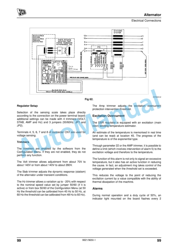
- 154. Alternator Terminal Connections ……………………………………………………87
- 155. 50Hz Connections …………………………………………………………………….87
- 156. 60 Hz Connections ……………………………………………………………………90
- 157. DSR Digital Regulator ………………………………………………………………….93
- 158. Introduction ………………………………………………………………………………93
- 159. Technical Characteristics ……………………………………………………………94
- 160. Technical Specifications ……………………………………………………………..95
- 161. Installation ………………………………………………………………………………..96
- 162. Excitation Overcurrent ……………………………………………………………….97
- 163. Alarms ……………………………………………………………………………………..97
- 164. Regulators ……………………………………………………………………………….98
- 165. DER1 Regulator ………………………………………………………………………….99
- 166. 50/60 Signal ……………………………………………………………………………101
- 167. Volt Trimmer ……………………………………………………………………………101
- 168. Stab Trimmer ………………………………………………………………………….101
- 169. Hz Trimmer …………………………………………………………………………….101
- 170. DER1 Connections ………………………………………………………………….101
- 171. Connections Based on Main Alternator Voltage …………………………..102
- 172. Protections ……………………………………………………………………………….103
- 173. Intervention of Protection Devices Causes ………………………………….103
- 174. Starting and Stopping The Operations ……………………………………………….104
- 175. Cleaning the Alternator ……………………………………………………………………105
- 176. Maintenance ………………………………………………………………………………….106
- 177. Internal and External Cleaning of the Generator …………………………….106
- 178. Fault Finding ………………………………………………………………………………….107
- 179. Engine – Care and Safety
- 180. Important Information ……………………………………………………………………..109
- 181. The Operator Manual …………………………………………………………………109
- 182. Safety Warnings ………………………………………………………………………..109
- 183. Safety, Yours and Others ………………………………………………………………… 110
- 184. Checklists …………………………………………………………………………………….. 111
- 185. General Safety …………………………………………………………………………. 111
- 186. Operating Safety ………………………………………………………………………. 112
- 187. Maintenance Safety …………………………………………………………………… 113
- 188. MTU Engine
- 189. Engine Safety ……………………………………………………………………………….. 119
- 190. Safety Requirements for Startup …………………………………………………. 119
- 191. Safety Requirements for Equipment Operation ……………………………… 119
- 192. Malfunctions and Emergency Stop ………………………………………………. 119
- 193. Operation …………………………………………………………………………………. 119
- 194. Operation of Electrical Equipment ……………………………………………….. 119
- 195. Safety Requirements Prior to Maintenance and Repair Work …………..120
- 196. Safety Requirements During Maintenance and Repair Work ……………120
- 197. Safety Requirements after Completion of Maintenance Work and Repair
- 198. Work ………………………………………………………………………………………..121
- 199. Welding Work ……………………………………………………………………………121
- 200. Hydraulic Installation and Removal ………………………………………………121
- 201. Working with Batteries ………………………………………………………………..121
- 202. Working on Electrical and Electronic Assemblies …………………………..121
- 203. Working with Laser Equipment …………………………………………………….122
- 204. MTU Engine
- 205. General Information ………………………………………………………………………..123
- 206. Engine Layout …………………………………………………………………………..123
- 207. Engine Model Designation ………………………………………………………….125
- 208. Engine Side and Cylinder Designations ………………………………………..126
- 209. Sensors and Actuators ……………………………………………………………….126
- 210. MTU Engine Fuels
- 211. Fuels – General Information ……………………………………………………………..129
- 212. Diesel Fuels …………………………………………………………………………………..130
- 213. Selection of a Suitable Diesel Fuel ……………………………………………….130
- 214. Limit Values for Water and Total Contamination ……………………………..130
- 215. Specifications for Distilate Fuels …………………………………………………..130
- 216. Low Sulfur Diesel Fuels ………………………………………………………………130
- 217. Winter Operation ……………………………………………………………………….130
- 218. Flow Improvers ………………………………………………………………………….131
- 219. Engine – Operation
- 220. Starting and Running ………………………………………………………………………133
- 221. At First Start ………………………………………………………………………………133
- 222. Checks Before Running ……………………………………………………………..133
- 223. Starting the Engine …………………………………………………………………….133
- 224. Starting at Low Temperatures ………………………………………………………133
- 225. At temperatures below 0°C: ………………………………………………………133
- 226. Coolant Temperature ………………………………………………………………….134
- 227. Oil Pressure ………………………………………………………………………………134
- 228. Charging Indicator Lamp …………………………………………………………….134
- 229. Putting the Engine Back In to Operation ……………………………………….135
- 230. After an Extended Period Out of Service (>3 Months) …………………..135
- 231. After a Scheduled Out of Service Period …………………………………….135
- 232. Operational Checks ……………………………………………………………………135
- 233. Engine Stop Test – Manual Operation ……………………………………………135
- 234. Stop Test Preparation ………………………………………………………………135
- 235. Stop Test ………………………………………………………………………………..135
- 236. Emergency Engine Shutdown ……………………………………………………..136
- 237. Emergency Engine Shutdown Test …………………………………………….136
- 238. After Emergency Shutdown ………………………………………………………136
- 239. Putting the Engine Out of Operation …………………………………………….136
- 240. Engine – Routine Maintenance
- 241. Lubricating Oil System …………………………………………………………………….137
- 242. Recommended Oils ……………………………………………………………………137
- 243. Engine Oil Capacity ……………………………………………………………………137
- 244. Checking the Oil Level ……………………………………………………………….138
- 245. Checking the Oil level Prior to Start ……………………………………………138
- 246. Oil Level Check after the Engine Has Stopped …………………………….138
- 247. Engine Oil – Change …………………………………………………………………..139
- 248. Draining the Oil at Drain Plug on Oil Pan ……………………………………139
- 249. Filling With New Oil ………………………………………………………………….139
- 250. Changing the Oil Filter ………………………………………………………………..140
- 251. Special Tools, Materials, Spare Parts ………………………………………….140
- 252. Engine Oil Filter – Replacement …………………………………………………140
- 253. Engine Cooling system ……………………………………………………………………141
- 254. Checking Engine Coolant Level (At Filler Neck) …………………………….141
- 255. Checking Engine Coolant Level (Using Level Sensor) …………………….141
- 256. Changing the Engine Coolant ……………………………………………………..142
- 257. Draining the Engine Coolant ……………………………………………………….142
- 258. Preparatory Steps ……………………………………………………………………142
- 259. Draining …………………………………………………………………………………142
- 260. Filling with Engine Coolant ………………………………………………………….143
- 261. Special Tools, Materials, Spare Parts ………………………………………….143
- 262. Preparatory Steps ……………………………………………………………………143
- 263. Filling …………………………………………………………………………………….143
- 264. Engine Coolant Pump – Relief Bore Check ……………………………………144
- 265. Air Cleaner …………………………………………………………………………………….145
- 266. Air Filter – Replacement ………………………………………………………………145
- 267. Air Filter – Removal and Installation ……………………………………………..145
- 268. Air Intake ………………………………………………………………………………………146
- 269. Service Indicator – Signal Ring Position Check ………………………………146
- 270. Fuel System …………………………………………………………………………………..147
- 271. Fuel System – Venting ………………………………………………………………..147
- 272. Fuel Filter …………………………………………………………………………………148
- 273. Special Tools, Material, Spare Parts …………………………………………..148
- 274. Fuel Filter – Replacement ……………………………………………………………148
- 275. Fuel Pre-Filter Replacement ……………………………………………………….148
- 276. Special Tools, Material, Spare Parts …………………………………………..148
- 277. Fuel Pre-Filter – Replacement ……………………………………………………148
- 278. Electrical system …………………………………………………………………………….149
- 279. Starter – Condition Check ……………………………………………………………149
- 280. Wiring (General) for Engine / Gearbox / Unit …………………………………149
- 281. Special Tools, Material, Spare Parts …………………………………………..149
- 282. Engine Wiring – Check ……………………………………………………………..149
- 283. Accessories for (Electronic) Engine Governor / Control System ……….150
- 284. Special Tools, Material, Spare Parts …………………………………………..150
- 285. Engine Governor and Connectors – Cleaning ………………………………150
- 286. Cleaning Severely Contaminated Connectors on the Engine Governor ..
- 287. 150
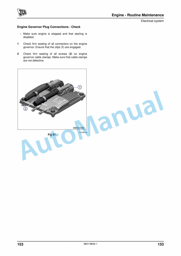
- 288. Engine Governor Plug Connections – Check ……………………………….151
- 289. Miscellaneous ………………………………………………………………………………..152
- 290. Checking Drive Belts ………………………………………………………………….152
- 291. Fan Drive – Adjusting the Belt Tension ………………………………………..152
- 292. Checking Belt Condition …………………………………………………………..152
- 293. Drive Belt – Tension










There are no reviews yet.